3
Owner´s Manual
Before completing the electrical connection, check the worm
(13) rotation. When the ON button is pressed, the worm
must rotate counter clockwise, seeing the equipment in
front. If the worm rotates clockwise, push the stop button
and unplug the equipment. Interchange 2 of 3 incoming
power supply wires. (See fig. 2)
Reconnect the grinder to the power supply, turn it on and
verify the rotation again. If the correct operation is
confirmed, fix the connection to the power supply. If you
have any question regarding the connection of the equip-
ment, contact to your authorized dealer. The above proce-
dure only applies to grinder with three phase connection.
HOW TO REMOVE GRINDING UNIT.
1. Remove the ring (17) turning it counterclockwise and extract the plate (16), Knife (15) and
worm (13).
2. Unscrew the headstock knob (7) (see Fig 4) to be able to remove the headstock (10).
Reverse the steps and sequence to install the grinding unit again. Taking special attention to the
next points :
a. After assembling the headstock (10), screw the headstock knob (7) to fix the headstock
b. The knife (15) must be inserted into worm’s shaft. The sharp end must face forward.
c. Place plate (19) centered against knife (18) assuring the notch matches the Headstock’s
inserted pin.
CAUTION!:
Unplug or disconnect the machine from the power supply before changing
wires.
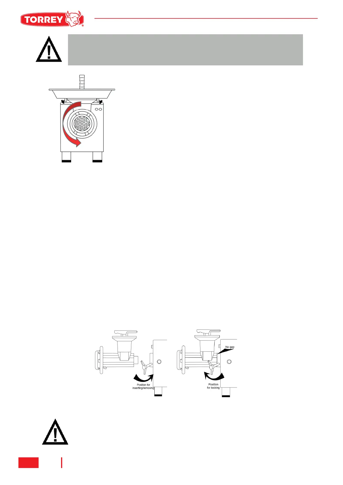
IMPORTANT!:
Before locking the headstock knob, be sure that both headstock (10) and
transmission cover (6) are joined with no gap between them.
M-32 | M-32-3 | M-32-5 | M-32AI | M-32-3AI | M-32-5AI
FIG.3 WORM ROTATION
FIG.4 POSITION FOR LEVER HANDLE
 Loading...