This document is a service manual for Toshiba Colour Televisions, specifically models 2555DB, 2855DB, 2552DB, and 2852DB, all utilizing the C5SR Chassis. It provides essential information for servicing, including safety instructions, technical specifications, installation and service adjustments, a ROM data list for IIC bus control, cabinet replacement parts lists, and circuit board diagrams.
The manual begins with critical safety instructions, emphasizing precautions related to X-ray radiation and general servicing. It warns that before servicing, technicians must read the "X-RAY RADIATION PRECAUTION," "SAFETY PRECAUTION," and "PRODUCT SAFETY NOTICE" sections.
X-Ray Radiation Precaution:
- E.H.T. Check: The E.H.T. (Extra High Tension) must be checked during every service to ensure the CRT does not emit X-ray radiation due to excessive voltage.
- Nominal E.H.T.: The nominal E.H.T. for this receiver is 26.5 kV at zero beam current (minimum brightness) when operating at 240V a.c.
- Maximum Permissible E.H.T.: The maximum permissible E.H.T. voltage under any operating circumstances must not exceed 29.0 kV. A "High Voltage Check" procedure using an accurate E.H.T. voltmeter is required.
- CRT Replacement: The only source of X-RAY radiation is the CRT. To prevent X-ray radiation, any replacement CRT must be identical to the original as specified in the Parts List.
- Safety-Related Components: Some components have safety-related characteristics that prevent X-ray radiation. For continued safety, replacements must be made only after referring to the Product Safety Notice.
General Safety Precaution:
- High Voltage: The receiver operates at a nominal E.H.T. voltage of 24.5 kV. Extreme caution is advised when working with the back removed. Servicing should only be performed by individuals conversant with high voltage equipment precautions.
- CRT Handling: Always discharge the anode to the chassis before removing the anode cap. If the CRT breaks, it can violently expel glass fragments, so shatter-proof goggles and extreme care are necessary. The CRT should not be held by its neck.
- Cable Forms: All cable forms must be replaced exactly as supplied from the factory to maintain safety.
- Mains Potential: A small part of the chassis operates at approximately half mains potential. For safety, the receiver should be supplied via a suitable isolating transformer of adequate rating when servicing or connecting test equipment.
- Fuses: Blown fuses must be replaced with the exact type specified in the parts list.
- Wiring: When replacing wires or components, leads should be wound around the terminal before soldering.
- Safety Components: Safety components, identified by international hazard symbols on the circuit diagram and parts list, must be Toshiba-approved types and mounted as original.
- Heat: Wires should be kept away from high-temperature components.
Product Safety Notice:
Many electrical and mechanical components have special safety-related characteristics, often unnoticed. Components with these characteristics are identified by international hazard symbols in the manual. Substituting non-specified components may create X-ray radiation.
Technical Specifications
Models 2555DB/2855DB:
- Input Power Rating: 100 watts (2555DB), 105 watts (2855DB), AC 220-240 volts, 50 Hz.
- Aerial Input Impedance: 75 ohm unbalanced type for UHF.
- Receiving Channels: PAL I Standard, UHF channels 21 to 68.
- Intermediate Frequencies:
- Picture I-F carrier frequency: 39.5 MHz
- Sound I-F carrier frequency: 33.5 MHz
- Colour sub-carrier frequency: 35.07 MHz
- Picture Tube:
- 2555DB: 25 inches, A59EAK71X01, 590 mm (diagonal of viewable area), 110° deflection.
- 2855DB: 28 inches, A66EAK71X01, 660 mm (diagonal of viewable area), 110° deflection.
- Sound Output: 10.0 watts x 2.
- Speakers:
- 2555DB: 160 mm x 40 mm oval 2 pcs (MAIN), 100 mm 2pcs (Hill Top).
- 2855DB: 120 mm x 60 mm oval 2 pcs (MAIN), 100 mm 2pcs (Hill Top).
- Aux. Terminals: 21 pin socket, S-VIDEO, VIDEO/AUDIO INPUT socket.
- Cabinet: Table type.
- Dimensions:
- 2555DB: Height 527.5 mm, Width 676 mm, Depth 440 mm.
- 2855DB: Height 571.3 mm, Width 760 mm, Depth 480 mm.
- Mass: 28.4 kg (2555DB), 37.7 kg (2855DB).
- Features: Video input of PAL/3.58N/4.43N, TELETEXT reception, NICAM Digital stereo system, OFF-timer.
Models 2552DB/2852DB:
- Input Power Rating: 100 watts (2552DB), 105 watts (2852DB), AC 220-240 volts, 50 Hz.
- Aerial Input Impedance: 75 ohm unbalanced type for UHF.
- Receiving Channels: PAL I Standard, UHF channels 21 to 68.
- Intermediate Frequencies:
- Picture I-F carrier frequency: 39.5 MHz
- Sound I-F carrier frequency: 33.5 MHz
- Colour sub-carrier frequency: 35.07 MHz
- Picture Tube:
- 2552DB: 25 inches, A59EAK71X01, 590 mm (diagonal of viewable area), 110° deflection.
- 2852DB: 28 inches, A66EAK71X01, 660 mm (diagonal of viewable area), 110° deflection.
- Sound Output: 10.0 watts x 2.
- Speakers:
- 2552DB: 160 mm x 40 mm oval 2 pcs (MAIN).
- 2852DB: 120 mm x 60 mm oval 2 pcs (MAIN).
- Aux. Terminals: 21 pin socket, S-VIDEO, VIDEO/AUDIO INPUT socket.
- Cabinet: Table type.
- Dimensions:
- 2552DB: Height 516 mm, Width 640 mm, Depth 447 mm.
- 2852DB: Height 568.5 mm, Width 700 mm, Depth 474 mm.
- Mass: 29.6 kg (2552DB), 33.0 kg (2852DB).
- Features: Video input of PAL/3.58N/4.43N, TELETEXT reception, NICAM Digital stereo system, OFF-timer.
Specifications are subject to change without notice.
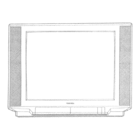
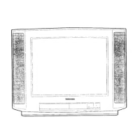
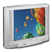
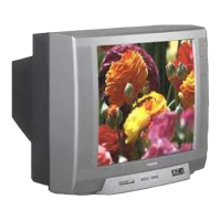
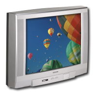
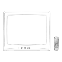
Usage Features (Front Controls and Rear Views)
The manual provides diagrams of the front controls and rear views for each model series (2555DB, 2855DB, and 2552DB/2852DB). Common controls and terminals include:
- Front Controls:
- VIDEO-3: S-VIDEO TERMINAL
- VIDEO-3: INPUT SOCKET
- MENU SELECT
- VOLUME DOWN/UP
- POSITION UP/DOWN
- MAINS SWITCH
- POWER INDICATOR
- REMOTE EYE
- HEAD PHONE (2855DB only)
- Rear Views:
- HORIZ. PICTURE POSITION
- AERIAL TERMINAL
- 21-pin SOCKET 2 (S-VIDEO/AV)
- 21-pin SOCKET 1 (FULL)
Maintenance Features (Installation and Service Adjustments)
General Information:
- Receivers are factory-checked for proper colour and B/W pictures. Minor adjustments may be needed based on location.
- Unpacking: Carefully remove the receiver from its carton and packing materials.
- Power-up: Plug into a 240 volts 50 Hz AC outlet. Turn ON and check/adjust customer controls (BRIGHTNESS, CONTRAST, COLOUR).
Automatic Degaussing:
- A degaussing coil is mounted around the picture tube. External degaussing is usually unnecessary after moving the receiver, provided it's properly degaussed upon installation.
- The degaussing coil operates for about 1 second after power ON.
- If the set is moved or faced in a different direction, switch off the power for at least 30 minutes for the degaussing circuit to operate properly.
- If colour purity issues persist, use an external degaussing coil. Slowly move it around the faceplate, sides, and front of the picture tube, then withdraw it to about 2m before disconnecting.
- If shading persists, perform COLOUR PURITY ADJUSTMENT and CONVERGENCE ADJUSTMENTS.
High Voltage Check:
- CAUTION: There is no HIGH VOLTAGE ADJUSTMENT on this chassis.
- Connect an accurate high voltage meter to the second anode of the picture tube.
- Turn on the receiver, set BRIGHTNESS and CONTRAST to minimum (zero beam current).
- High voltage should be below 29.0 kV.
Horizontal Centre Adjustment:
- Receive the UK PHILIPS pattern.
- Set contrast, colour, and brightness to centre.
- Adjust H. CENTER USER Control (R452) to centre the pattern on the screen.
Focus Adjustment:
- Adjust FOCUS Control on FLYBACK TRANS. (T461) for well-defined scanning lines in the centre area of the screen.
SIF FM DET (LG04) Adjustment (NICAM Board):
- Connect SIF generator (0.01 µF capacitor) to pin DI of PD01 on NICAM Board.
- Connect oscilloscope to pin 9 of ICD03.
- Set SIF generator: Sound carrier frequency 6.0 MHz, Modulation frequency 1000 Hz, Frequency deviation ±15 kHz, Signal level 100 dBµ (50 ohm load).
- Adjust LG04 for maximum response of 1000 Hz det-out on scope.
PAL Matrix Adjustment:
- Tune in a Philips pattern colour programme.
- Set COLOUR Control for proper colour.
- If Venetian Blind appears, adjust DL PHASE ADJ. Coil (L551) to minimize it.
- Next, adjust 1H-DL ADJ. VR (R551) to minimize the Blind.
- Repeat steps 5 and 6 if the Blind persists, adjusting R551 and L551 until it disappears.
CRT Grey Scale Adjustment:
- Tune in an active channel.
- Set SERVICE SW. (S202) to "H. LINE" position.
- Turn SCREEN Control (on T461) fully counter-clockwise.
- Rotate RED, GREEN, and BLUE CUT OFF Controls (R557, R558, R559) to mid position.
- Set GREEN and BLUE DRIVE Controls (R252, R253) to centre.
- Rotate SCREEN Control clockwise until the first line appears slightly on the screen. Set it to this position.
- Adjust CUT OFF Controls to obtain slightly lighted horizontal lines in the same levels of three colours (RED, GREEN, and BLUE). Lines may appear white if adjusted properly.
- Set SERVICE SW. (S202) to "RECEIVE" position.
- Set CONTRAST and COLOUR Controls to minimum, and BRIGHTNESS Control to maximum.
- Adjust BLUE and GREEN DRIVE Controls (R252/R253) for proper white-balanced picture in high light areas.
- Set BRIGHTNESS and CONTRAST Controls for dark grey raster. Check white balance in low brightness. If not proper, retouch CUT OFF and DRIVE Controls for good white balance in both low and high light areas.
Sub-Brightness Adjustment:
- Tune in a colour programme.
- Set CONTRAST Control to minimum and BRIGHTNESS Control to centre.
- Set COLOUR Control to centre.
- Set SUB-BRIGHT. Control (R255) to centre and leave the receiver for five minutes.
- Adjust SUB-BRIGHT. Control to a position where the picture shows no blooming in high bright areas and is not too dark in low bright areas.
- Check picture variation by rotating CONTRAST and BRIGHTNESS Controls to both extremes.
- If the picture is not dark with CONTRAST and BRIGHTNESS Controls at minimum, or not bright at maximum, adjust SUB-BRIGHT. Control again for an acceptable picture.
Extension Cable Set:
- An Extension Cable Set (Part No. 23305270) is available for servicing modules of C2DB chassis. For 2545DB chassis, it's used for the CHROMA Board.
- Pins are identified by surface-print on the cable set's PC board.
- Usage:
- Unsolder corners of the module's shielding case.
- Remove the shielding case and pull up the module to disconnect.
- Connect the Extension Cable Set to the module and Main board.
Chassis Stand for Repair:
- 2555DB/2855DB:
- Disconnect speaker lead wires from the degausser coil (three omega clips).
- Lift slightly and pull out the chassis from the front mask.
- Insert the hook at the right side of the chassis into the slit at the left front of the bottom side of the front mask.
- To restore, reverse these steps.
- 2852DB/2552DB:
- Remove the wire set for the loud speaker from the holder.
- Remove the horn speaker unit (unscrew fixing screws).
- Lift the chassis to stand against the inner side surface of the front mask.
- Screw the chassis to the side of the front mask using screws removed earlier.
- To restore, reverse these steps.
Service Mode General Instructions:
- Entering Service Mode:
- Press the "star" button once on the Remote Control.
- Press the "star" button again and keep pressing.
- Keep pressing the "star" button, then press the MENU button on the TV set.
- The service mode display (e.g., "11 03 M00|..........") will appear.
- Selecting Adjusting Items: Press the CHANNEL ▲ button to cycle through adjustment items (▼ for reverse order).
- Adjusting Data: Press the VOLUME ▲ or ▼ button to change data values from 00 to FF (variable range depends on the item).
- Normal Operation: Press the MENU button on the TV.
- Exiting Service Mode: Press the POWER button on the remote control to turn off the TV.
Sub Data Additional Description:
The manual includes a table describing various service mode symbols and their corresponding adjustments, such as:
- HIT: V amplitude adjustment.
- LIN: V linearity correction 1, linearity balance between top and bottom screen.
- VSC: V linearity correction 2, linearity balance between top/bottom and center.
- VPC: V picture position adjustment.
- VCP: Setting of amount of V amplitude correction against variation of screen brightness.
- WID: H amplitude adjustment.
- DPC: H pin-cushion distortion correction.
- CNR: H pin-cushion distortion correction at four corners.
- KEY: Pedestal distortion correction.
- HCP: Setting of amount of H amplitude correction against variation of screen brightness.
- VMC: V linearity correction, linearity balance at 1/4, 3/4 areas from top.
The ROM Data List for IIC Bus Control provides reference values for various settings (MODE 0, MODE 1, HEIGHT, V. LINEARITY, V. POSITION, H. WIDTH, DPC, KEYSTONE, etc.) for each model. Items marked with an asterisk (*) should be adjusted.
Parts Lists and Diagrams
The manual includes comprehensive parts lists for cabinet replacement, chassis replacement (capacitors, resistors, coils & transformers, semiconductors, miscellaneous), and detailed circuit block diagrams, PC board layouts (bottom foil side for Signal Board, Power/Def/Audio Board, CRT Drive Board, Chroma Board), and terminal views of transistors.