EasyManua.ls Logo

Toshiba 29A3DE User Manual

Toshiba 29A3DE
6 pages
To Next Page IconTo Next Page
Page #1 background imageLoading...
Page #1 background image
SCHEMATIC DIAGRAM MODEL : 29A3DE / 29A3E / 29A3SH
WARNING: BEFORE SERVICING THIS CHASSIS, READ THE "X-RAY RADIATION PRECAUTION", "SAFETY
PRECAUTION" AND "PRODUCT SAFETY NOTICE" ON THE MANUAL FOR THIS MODEL.
CAUTION: The international hazard symbols "*" in the schematic diagram and the parts list designate components
which have special characteristics important for safety and should be replaced only with types identical to those in the
original circuit or specified in the parts list. The mounting position of replacements is to be identical with originals.
Before replacing any of these components, read carefully the PRODUCT SAFETY NOTICE on the MANUAL for this
model. Do not degrade the safety of the receiver through improper servicing.
4. Voltages read with DIGITAL MULTI-METER from point indicated to chassing ground, using a color bar signal with all
controls at normal, line voltage 220 volts.
5. Waveforms are taken receiving color bar signal with enough sensitivity.
6. Voltage reading shown are nominal values and may vary ±20% except H.V.
NOTE:
1. RESISTOR Resistance is shown in ohm [K = 1.000, M = 1.000.000]. All resistors are 1/6W and 5%
tolerance carbon resistor, unless otherwise noted as the following marks.
1/2R = Metal or Metal oxide of 1/2 watt 1/2S = Carbon compsistion of 1/2 watt
1RF = Fuse resistor of 1 watt 10W = Cement of 10 watt
K = ±10% G = ±2% F = ±1%
2. CAPACITOR Unless otherwise noted in schematic, all capacitor values less than 1 are expressed in
?F, and the values more than 1 in pF.
All capacitors are ceramic 50V, unless otherwise noted as the following marks.
Electolytic capacitor Mylar capacitor
3. The parts indicated with " * " have special characteristics, and should be replaced with identical parts only.
Question and Answer IconNeed help?

Do you have a question about the Toshiba 29A3DE and is the answer not in the manual?

Toshiba 29A3DE Specifications

General IconGeneral
Screen Size29 inches
Display TechnologyCRT
Aspect Ratio4:3
Input/Output ConnectorsRF
Weight32 kg

Summary

Schematic Diagram Notes and Symbols

Resistor Value and Type Explanations

Explains resistance values, tolerances, and types of resistors used in the schematic.

Capacitor Value and Type Explanations

Details capacitor values, tolerances, voltage ratings, and types like ceramic and electrolytic.

Special Characteristic Components

Highlights components with special safety characteristics requiring identical replacements.

Voltage and Waveform Reading Conventions

Defines how voltage and waveform readings are taken for diagnosis and testing.

Service Mode Operation

Entering Service Mode

Step-by-step guide on how to enter the service mode using the remote control and TV buttons.

Displaying the Adjustment Menu

Instructions on how to access and display the adjustment menu on the TV screen.

Service Mode Key Functionality

Details the key entry functions and their special operations within the service mode.

Service Mode Adjustments and Testing

Selecting Adjustment Items

Procedure for selecting different adjustment items within the service mode using channel buttons.

Adjusting Data Values

How to change data values for selected adjustment items using volume buttons.

Exiting Service Mode

Instructions on how to properly exit the service mode by powering off the TV.

Memory Data Initialization (QA02)

Guide for initializing the QA02 memory data after replacement, including caution notes.

Test Signal Selection and Patterns

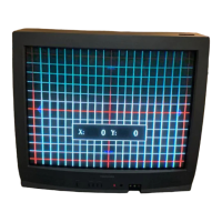
How to select and display built-in test patterns for signal analysis in service mode.

Self-Diagnostic Function

Initiating Self-Diagnostic

How to start the self-diagnostic function using the remote control's '9' button.

Interpreting Diagnostic Displays

Explanation of the diagnostic displays, including BUS line, POWER, BUS CONT, and BLOCK status.

Diagnostic Troubleshooting Notes

Notes on interpreting indicator colors (Green/Red) and troubleshooting based on blinking power indicators.

Design Mode Operation

Entering Design Mode

Procedure for entering the design mode by selecting service mode and pressing specific buttons.

Selecting Design Mode Items

Method for selecting items within design mode using channel buttons, referencing adjustment tables.

Adjusting Design Mode Data

How to adjust data values for design mode items using volume up/down buttons.
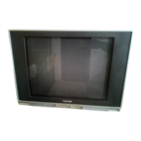
Related product manuals