Do you have a question about the Toshiba A90-0132 and is the answer not in the manual?
General safety and installation guidelines, avoiding specific locations, and R407C unit handling.
Specifications and models for outdoor units, including inverter and fixed-speed types.
Details on combined outdoor units, their HP, models, cooling capacity, and connectivity.
Lists various branching joints and headers with their model names, usage, and appearance details.
Specifies operating temperature ranges for cooling and heating, room temperature, and humidity.
Covers model naming conventions, combined unit ranges, combination restrictions, and mode priority settings.
Illustrates flexible branching configurations like line, header, and combined line/header branching for installation.
Highlights compact design, large capacity, advanced communication, self-diagnostics, high lift, multiple units, and intelligent control.
Detailed specifications for various indoor unit types, including model names, capacity codes, cooling, and heating capacities.
Lists parts and specifications for outdoor units, covering compressors, valves, motors, sensors, and heaters.
Details specific parts for Built-In Duct indoor units (MM-B140, B112, B080, B056) including motors, sensors, and PCBs.
Lists parts for Ceiling Type indoor units (MM-C/CR series) like fan motors, sensors, control PCBs, and transformers.
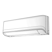
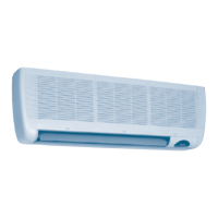
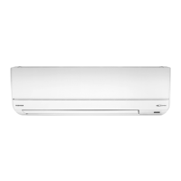
Details parts for High Wall indoor units (MM-K/KR series), including fan motors, capacitors, pulse motor valves, sensors, and PCBs.
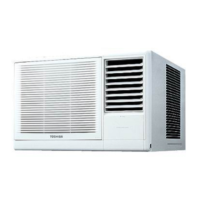
Lists parts for Chassis Type indoor units (MM-N series), such as fan motors, capacitors, pulse motor valves, sensors, and PCBs.
Details parts for Low Wall indoor units (MM-S/SR series), including fan motors, capacitors, pulse motor valves, sensors, and PCBs.
Lists parts for 2-Way Cassette indoor units (MM-TU series), including fan motors, capacitors, pulse motor valves, sensors, and PCBs.
Details parts for 4-Way Cassette indoor units (MM-U series), such as fan motors, capacitors, pulse motor valves, sensors, and PCBs.
Provides dimensional drawings, fixing bolt details, and piping connection details for outdoor units.
Shows dimensions, hanging bolt pitch, and installation space requirements for Built-In Duct indoor units.
Provides dimensional drawings, air outlets, and installation details for the Built-In Slim Duct indoor unit.
Shows dimensions, hanging bolt pitch, and installation space requirements for Low Wall indoor units.
Provides dimensional drawings, fixing locations, and air intake/outlet details for Chassis indoor units.
Shows dimensions, hanging bolt pitch, and installation space requirements for Ceiling indoor units.
Provides dimensional drawings, piping holes, and installation space requirements for High Wall indoor units.
Shows dimensions, ceiling openings, hanging bolt pitch, and installation space for 2-Way Cassette indoor units.
Provides dimensional drawings, duct sizes, and installation details for 4-way cassette indoor units.
Shows dimensions, duct sizes, and installation details for 4-way cassette indoor units.
Detailed wiring diagrams for inverter outdoor units, showing connections to components like compressors, fans, and control boards.
Wiring diagrams for fixed-speed outdoor units, detailing connections for compressors, fans, sensors, and control boards.
Wiring diagrams for 6 HP fixed-speed outdoor units, illustrating connections for key components and control boards.
Wiring diagrams specific to inverter outdoor units for cooling-only operation, showing component connections.
Wiring diagrams for fixed-speed outdoor units in cooling-only mode, detailing component and control board connections.
Wiring diagrams for Built-In Duct indoor units, illustrating connections for fan motors, sensors, valves, and control PCBs.
Wiring diagrams for Ceiling Type indoor units, showing connections for fan motors, sensors, valves, and control boards.
Wiring diagrams for High Wall indoor units, detailing connections to components like fan motors, sensors, and control PCBs.
Wiring diagrams for Chassis indoor units, illustrating connections for fan motors, sensors, valves, and control boards.
Wiring diagrams for Built-In Slim Duct indoor units, showing connections for fan motors, sensors, valves, and control PCBs.
Wiring diagrams for Low Wall indoor units, detailing connections to components like fan motors, sensors, and control boards.
Wiring diagrams for 4-Way Cassette indoor units, illustrating connections for fan motors, sensors, valves, and control boards.
Wiring diagrams for 2-Way Cassette indoor units, showing connections for fan motors, sensors, valves, and control PCBs.
Systematic diagram of refrigerant piping for inverter outdoor units in heat pump mode, showing all components and flow.
Systematic diagram of refrigerant piping for fixed-speed outdoor units (10/8 HP) in heat pump mode, detailing component connections.
Systematic diagram of refrigerant piping for 6 HP fixed-speed outdoor units in heat pump mode, showing component flow.
Systematic diagram of refrigerant piping for inverter outdoor units in cooling-only mode, illustrating component flow.
Systematic diagram of refrigerant piping for fixed-speed outdoor units (10/8 HP) in cooling-only mode, showing component connections.
Diagram showing refrigerant flow for a combined system in normal heat pump cooling mode, including indoor units and multiple outdoor units.
Shows refrigerant flow during emergency operation when the master inverter unit fails, with slave units operating.
Illustrates refrigerant flow during emergency operation when a fixed-speed unit fails, with other units compensating.
Diagram for refrigerant recovery from a failed outdoor unit in a multi-unit system, detailing the process for heat pump operation.
Schematic showing refrigeration cycle components within indoor units, with tables for pipe sizes and PMV codes.
Describes outdoor unit operation sequences for start/stop and thermostat ON/OFF states, detailing component actions.
Explains electronic expansion valve (PMV) control, pulse motor valve (PMV B) control, and cooling fan control logic.
Covers heating fan control, capacity calculation, and oil level detection/control mechanisms for outdoor units.
Details oil equalizing control between units and refrigerant/oil recovery control during operation for system health.
Explains SV2 release valve control for gas balance and compressor case bypass, plus fixed-speed compressor release control.
Describes compressor winding heating control to prevent oil stagnation and crank case heater control for fixed-speed units.
Explains IPDU controls for inverter compressors, including current release, heat sink temp, over-current, and high pressure SW control.
Details the reverse heat defrost method, including conditions for starting, system operation, and completion of defrost.
Covers defrost control details, cold draft prevention, and indoor unit heat exchanger heat removal operations.
Provides cautions for low ambient cooling operation and detailed instructions for handling Pulse Motor Valves (PMV).
Explains indoor unit controls including power reset setup, operation selection, room temperature control, automatic capacity, and capacity correction.
Covers air volume control, freeze prevention, oil/refrigerant recovery, intermittent operation, and drain pump control for indoor units.
Details auto louvre control, frequency fix operation, filter display, standby mode indicators, and central controller selection options.
Explains system information displayed on the inverter unit via rotary switches, covering refrigerant type, capacity, and unit counts.
Details operational data displayed on each outdoor unit via switches, including check codes, compressor types, operation modes, and valve outputs.
Explains outdoor cycle data displayed for fixed-speed units, covering check codes, compressor status, capacity, and oil level judgment.
Describes information displayed on the inverter unit for indoor communication, check codes, horsepower, demand commands, PMV opening, and sensor data.
Explains the function and display of LEDs on the indoor PC board (MCC-1361-01) for serial receive, serial send, alarm, and communication.
Describes remote controller standby display conditions and the indoor PMV full open/full close functionality.
Details factory default switch positions for indoor units (SW01-SW08) for functions like unit number, network address, and TA adjust.
Provides tables for network address setup via DIP switch (SW02) and indoor unit HP setup via SW08.
Explains how to select the correct PC board (MCC-1361-01) based on model, switch settings, and jumper configuration.
Guides on reading check codes and status from the remote controller, including standby modes and switch functions.
Explains how to interpret check codes and filter data displayed on the remote controller's 7-segment display.
Lists self-diagnostic check codes for indoor units, outdoor IPDU, inverter, and fixed-speed units with their corresponding causes.
Provides a step-by-step procedure to diagnose and resolve the "Inverter serial signal short circuit" error.
Outlines diagnostic steps for "Drain pump fault" and "Indoor sensor (TA) short or open circuit alarm".
Provides diagnostic procedures for "Indoor fan motor short circuit alarm" and "Indoor PC board short circuit alarm".
Outlines the diagnostic steps for the "G-Tr short circuit protective operation alarm".
Details diagnostic steps for "Current detection circuit alarm", "Outdoor heat exchanger sensor (TE) short circuit", and "Extension IC, EEPROM short circuit alarm".
Provides a diagnostic procedure for the "Compressor error alarm".
Outlines the diagnostic steps for "Compressor break down".
Provides diagnostic steps for the "Inverter high pressure SW circuit alarm".
Outlines the diagnostic steps for "High pressure protective operation".
Details diagnostic steps for "Missing phase" and "Indoor over capacity" errors.
Outlines diagnostic steps for "Reduction in the No. of connected outdoor units" and "Outdoor unit connection over limit".
Details diagnostic steps for "Server outdoor address incorrect", "Indoor TC1 sensor short circuit", and "Indoor TC2 sensor short circuit".
Provides a diagnostic procedure for the "Indoor/outdoor communication short circuit" error.
Outlines the diagnostic steps for "No. of connected indoor units over capacity".
Provides diagnostic steps for the "Central management communication short circuit" error.
Outlines the diagnostic steps for "Central management address set-up fault".
Provides diagnostic steps for the "Remote controller serial signal circuit alarm".
Details diagnostic steps for "Indoor unit miswiring/misconnection" and "Refrigerant circulation amount shortage judgement".
Outlines diagnostic steps for TD1, TD2, and TS sensor short circuit errors.
Provides diagnostic steps for the "Discharge temperature TD1 alarm".
Details diagnostic steps for "Suction temperature (TS) alarm" and "High pressure sensor (Pd) short circuit".
Outlines the diagnostic steps for "Pressure sensor (Pd/Ps) miswiring".
Details diagnostic steps for "Low Hz time discharge temp. (TD1) alarm" and "Outdoor unit power source phase order miswiring".
Outlines diagnostic steps for Ps sensor errors, external display faults, and indoor pressure sensor issues.
Provides diagnostic steps for the "Discharge temperature (TD2) alarm".
Outlines diagnostic steps for "Mg-SW protective operation".
Provides diagnostic steps for "Low pressure (Ps) protective operation".
Outlines the diagnostic steps for the "Master outdoor unit set-up alarm".
Details diagnostic steps for slave unit alarms, TH sensor, and oil temperature sensor errors (TK1, TK2, TK3).
Provides diagnostic steps for "Low oil level detection".
Outlines the diagnostic steps for "Oil temperature (TK1) detection alarm".
Provides diagnostic steps for the "Oil temperature (TK2) detection alarm".
Details a procedure to check for oil tank circuit leakage or blockage using interface PC board settings and temperature checks.
Outlines the diagnostic steps for "Abnormal overheat of heat sink".
Provides diagnostic steps for "SV3C valve blockage detection".
Outlines the diagnostic steps for "SV3C valve leakage detection".
Provides diagnostic steps for "Outdoor PMV refrigerant leakage detection".
Outlines diagnostic steps for "Indoor address undefined" and "Outdoor address undefined" errors.
Details diagnostic steps for fixed-speed high pressure SW system alarms.
Provides diagnostic steps for the "Inverter IOL short circuit".
Outlines diagnostic steps for fixed-speed IOL and OCR alarms.
Explains the outdoor unit 7-segment display function and the procedure for checking and clearing emergency stop conditions.
Provides functional outlines and descriptions for key components like solenoid valves, check valves, PMV, sensors, and balancing pipes.
Details the procedure for emergency operation when one compressor fails, including DIP switch settings for back-up.
Outlines emergency process for a failed fixed-speed unit and back-up setup for the inverter unit.
Details the procedure for emergency operation when an inverter unit fails, including master unit selection and DIP switch settings.
Describes a simplified method for outdoor back-up setup during cooling season when interface or circuit systems fail.
Details oil tank circuit errors, operation procedure, and oil level judgment results, including diagrams of peripheral circuits.
Outlines the procedure for leak testing refrigerant pipes, including pressure requirements, test methods, and leak location checks.
Details the vacuuming process for refrigerant pipes, including pump requirements, duration, and checks for leaks.
Explains how to calculate the amount of additional refrigerant needed based on pipe size and length, with an example calculation.
Describes the method for charging additional refrigerant into the system, including hose connections and valve operations.
Provides a reference chart for calculating additional refrigerant amounts based on pipe diameter and length.
Outlines the overall procedure for trial operation, including initial checks and implementation steps.
Details checks for power supply, remote controller display, alarm codes, and fan operation during trial runs.
Describes checks for cooling operation, including air discharge, circulation, temperature differences, voltage, current, and pressure.
Defines criteria for normal operation based on temperature difference, current values, and operating pressures during trial runs.
Explains the automatic addressing process between outdoor and indoor units, including timing, cautions, and conditions for reactivation.
Details a function to check refrigerant pipe and control line connections between indoor and outdoor units using interface PC board switches.
Describes a function to start/stop indoor units collectively or individually from the outdoor unit via interface PC board switches.
Explains the function to collectively change indoor unit modes to trial cooling operation using interface PC board switches.
Details the function for collectively starting or stopping indoor units using interface PC board switches on the outdoor unit.
Explains the function to individually start or stop indoor units using interface PC board switches, referencing address tables.
Describes methods to clear check code alarms from the remote controller and the inverter outdoor unit's interface PC board.
Details clearing alarms by power reset and identifying remote controllers connected to outdoor units.
Explains manual PMV full open/close functions for both indoor and outdoor units via PC board operations.
Details the method for recovering refrigerant from a failed outdoor unit in a multi-unit system, including notes on ratios and PMV status.
Explains refrigerant recovery procedures when back-up operation is utilized, covering master unit selection and trial operation steps.
Provides explanatory diagrams showing the open/close direction and position of service valves on modular multi systems.
Outlines the general steps for compressor replacement, from refrigerant recovery to charging.
Details the process for removing parts, extracting oil, and physically removing the compressor from the front of outdoor units.
Specific steps for removing parts, extracting oil, and removing the compressor for MM-A0160HX/CX outdoor units.
Details the process for removing parts, extracting oil, and physically removing the compressor from the rear of outdoor units.
Covers installation of the new compressor, vacuuming, and refrigerant charging after replacement.
Specific steps for removing the compressor from MM-A0160HX/CX units, including parts removal and extraction of oil.
Details installation, vacuuming, and refrigerant charging for MM-A0160HX/CX units after compressor replacement.
Provides a step-by-step guide for replacing the interface PC board, including connector removal, jumper link cutting, and installation.
An exploded view diagram of outdoor units with numbered parts for identification.
A detailed list of service parts for outdoor units (MM-A0280HT, etc.), referencing part numbers and models.
An exploded view diagram for MM-A0160HX/CX outdoor units with numbered parts for identification.
A detailed list of service parts for MM-A0160HX/CX outdoor units, referencing part numbers and models.
Diagrams showing the assembly of electrical parts for various outdoor unit models.
A detailed list of electrical parts for outdoor units, referencing part numbers and models.
An exploded view diagram of Built-In Duct indoor units with numbered parts for identification.
A detailed list of service parts for Ceiling Type indoor units, referencing part numbers and models.
An exploded view diagram of High Wall indoor units with numbered parts for identification.
A detailed list of service parts for High Wall indoor units, referencing part numbers and models.
An exploded view diagram of Low Wall indoor units with numbered parts for identification.
A detailed list of service parts for Built-In Slim Duct indoor units, referencing part numbers and models.
An exploded view diagram of 2-Way Cassette indoor units with numbered parts for identification.
A detailed list of service parts for 4-Way Cassette indoor units (MM-U056, MM-U080), referencing part numbers.
An exploded view diagram for 4-Way Cassette indoor units (MM-U112, MM-U140) with numbered parts for identification.
A list of parts for the ceiling panel (RBC-U133PG(W)-PE), referencing part numbers and descriptions.
A list of parts for ceiling panels (RBC-U264PG/PGR(W)-E), referencing part numbers and models.
A list of parts for ceiling panels (RBC-U464PG/PGR(W)-E), referencing part numbers and models.
| Brand | Toshiba |
|---|---|
| Model | A90-0132 |
| Category | Air Conditioner |
| Language | English |