EasyManua.ls Logo

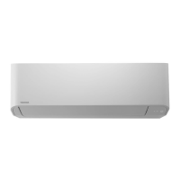
Toshiba MMK-AP0072H User Manual

Toshiba MMK-AP0072H
91 pages
To Next Page IconTo Next Page
Page #1 background imageLoading...
Page #1 background image
R410A
FILE NO. A05-012
OWNER’S MANUAL
/
INSTALLATION MANUAL
Indoor Unit
<4-way Air Discharge Cassette Type>
MMU-AP0091H, AP0121H, AP0151H,
MMU-AP0181H, AP0241H, AP0271H,
MMU-AP0301H, AP0361H, AP0481H
MMU-AP0561H
<2-way Air Discharge Cassette Type>
MMU-AP0071WH, AP0091WH, AP0121WH,
MMU-AP0151WH, AP0181WH, AP0241WH,
MMU-AP0271WH, AP0301WH, AP0481WH*
* CHINA market only
<1-way Air Discharge Cassette Type>
MMU-AP0071YH, AP0091YH, AP0121YH,
MMU-AP0151SH, AP0181SH, AP0241SH,
MMU-AP0152SH, AP0182SH, AP0242SH
<Concealed Duct Standard Type>
MMD-AP0071BH, AP0091BH, AP0121BH, AP0151BH,
MMD-AP0181BH, AP0241BH, AP0271BH, AP0301BH,
MMD-AP0361BH, AP0481BH, AP0561BH
<Concealed Duct High Static Pressure Type>
MMD-AP0181H, AP0241H, AP0271H,
MMD-AP0361H, AP0481H
<Slim Duct Type>
MMD-AP0071SPH, AP0091SPH, AP0121SPH,
MMD-AP0151SPH, AP0181SPH
<Under Ceiling Type>
MMC-AP0151H, AP0181H, AP0241H,
MMC-AP0271H, AP0361H, AP0481H
<High Wall Type>
MMK-AP0071H, AP0091H, AP0121H,
MMK-AP0151H, AP0181H, AP0241H,
MMK-AP0072H, AP0092H, AP0122H
<Floor Standing Cabinet Type>
MML-AP0071H, AP0091H, AP0121H,
MML-AP0151H, AP0181H, AP0241H
<Floor Standing Concealed Type>
MML-AP0071BH, AP0091BH, AP0121BH,
MML-AP0151BH, AP0181BH, AP0241BH
<Floor Standing Type>
MMF-AP0151H, AP0181H, AP0241H,AP0271H,
MMF-AP0361H, AP0481H, AP0561H
Outdoor Unit
<Inverter Unit>
MMY-MAP0802FT8
MMY-MAP1002FT8
MMY-MAP1202FT8
Heat Recovery Type
PRINTED IN JAPAN, Aug, 2005 ToMo
The indoor unit in Super Heat Recovery Multi System is common to one in Super Modular Multi System air conditioner.
Therefore refer to the service manuals for A03-009, A03-010, and A03-011 separately issued.
System air conditioner
Flow Selector Unit (FS unit)
RBM-Y1122FE
RBM-Y1802FE
RBM-Y2802FE

Other manuals for Toshiba MMK-AP0072H

Questions and Answers:

Toshiba MMK-AP0072H Specifications

General IconGeneral
Cooling Capacity (BTU/h)24000
Voltage (V)220-240
Energy Efficiency Ratio (Cooling)3.21
Energy Efficiency Ratio (Heating)3.61
RefrigerantR32
Indoor Unit Weight13 kg
TypeSplit System
Power Supply220V, 50Hz

Summary

SAFETY PRECAUTIONS

Installation Warnings

Covers warnings on installation, use, moving/repair procedures.

Installation Cautions

Covers cautions on installation and fixing method.

REMOTE CONTROLLER OPERATION

Remote Controller Display

Explains indicators and display sections of the remote controller.

TIMER OPERATION

Timer Types and Setup

Explains timer modes and their setup.

INSTALLATION GUIDELINES

Installation Location Requirements

Requirements for choosing a suitable installation location.

Electrical Wiring Requirements

Warnings and cautions related to electrical wiring.

MAINTENANCE PROCEDURES

Maintenance Safety Warning

Crucial safety warning before performing maintenance.

OPERATIONS AND PERFORMANCE

OPERATING CONDITIONS AND RE-INSTALLATION

Operating Condition Limits

Specifies temperature and humidity limits for proper operation.

Re-installation Warnings

Details dangers and prohibited installation locations.

TROUBLESHOOTING GUIDE

Symptom-Cause Analysis

Lists common symptoms and their potential causes.

Troubleshooting Checks

Guides for common issues like auto-operation or insufficient cooling/heating.

ERROR CONFIRMATION

Check Code Display

How check codes appear on the remote controller.

Error History Confirmation

Procedure to check past error history.

DETAILED SAFETY CAUTIONS

Installation and Handling Warnings

Critical safety warnings for installation, refrigerant handling, and wiring.

Cautions for Installation Environment

Specific cautions regarding gas leaks and tool usage.

NEW REFRIGERANT INSTALLATION

Required Tools and Handling

Necessary tools and handling precautions for R410A.

INSTALLATION SITE SELECTION

Site Selection Criteria

Requirements for choosing a suitable installation location.

Installation Space Guidelines

Specifies required clearances and space for installation.

OUTDOOR UNIT INSTALLATION

Installation Site and Drainage

Requirements for outdoor unit placement and drainage.

Unit Anchoring and Spacing

How to secure units and spacing requirements.

OUTDOOR UNIT CONNECTIONS

REFRIGERANT PIPING

Refrigerant Pipe Connection

Steps for connecting refrigerant pipes to the outdoor unit.

Piping Requirements and Torque

Essential requirements for brazing and tightening torque.

PIPE CONNECTION AND FLARE MACHINING

PIPE SIZING AND CAPACITY MATCHING

REFRIGERANT PIPING TESTS

Airtight Test Procedure

Steps for performing an airtight test on the refrigerant lines.

Gas Leak Detection

How to check for gas leaks using detectors.

AIR PURGE PROCEDURE

Vacuum Pump Method

Detailed steps for purging air using a vacuum pump.

Vacuum Pump Requirements

Specifications for the vacuum pump to be used.

REFRIGERANT CHARGING

Calculating Refrigerant Amount

How to calculate the additional refrigerant needed.

Refrigerant Charging Process

Steps and precautions for charging refrigerant.

REVISED SAFETY CAUTIONS

ELECTRICAL WORK GUIDELINES

Earth Leakage Breaker Caution

Emphasizes the need for an earth leakage breaker.

Wiring Requirements and Specifications

Covers general requirements, wire connections, and power supply specs.

CONTROL WIRING AND GROUP CONTROL

SYSTEM WIRING DIAGRAM

System Wiring Overview

A visual representation of the complete system wiring.

POWER AND CONTROL WIRE CONNECTION

Connecting Power and Control Wires

Procedure for connecting power supply and control wires.

SYSTEM WIRING DIAGRAM DETAILS

System Wiring Configuration

Detailed wiring diagram for group control.

ADDRESS SETUP PROCEDURE

Automatic Address Setup Overview

Explains the automatic address setup process.

MANUAL ADDRESS SETUP AND SWITCHES

SWITCH SETUP AND RELAY CONNECTIONS

REMOTE CONTROLLER ADDRESS SETUP

CHANGING INDOOR ADDRESS

BULK INDOOR ADDRESS CHANGE

MULTIPLE INDOOR UNIT SETUP WITH FS UNIT

COOLING ONLY UNIT SETUP

TEST OPERATION GUIDE

TROUBLESHOOTING AND ERROR CODES

Segment Display and Check Codes

Explains outdoor unit segment display and check codes.

Outdoor Unit Error Codes [B]

Lists check codes displayed on the outdoor unit.

DETAILED ERROR CODE ANALYSIS

Outdoor Unit Error Codes H01-H16

Lists specific error codes and their meanings.

Outdoor Unit Error Codes L04-P29

Continues the list of error codes.

ACCESSORIES AND REFRIGERANT CAUTIONS

GENERAL SAFETY WARNINGS

Installation Safety Warnings

Critical safety warnings for installation professionals.

NEW REFRIGERANT INSTALLATION (REVISITED)

Tools and Handling for R410A

Essential tools and precautions for R410A.

INSTALLATION PLACE SELECTION (REVISITED)

Combustible Gas Leak Caution

Warning about installing near potential gas leaks.

INSTALLATION SPACE DIMENSIONS

FLOW SELECTOR UNIT INSTALLATION

FLOW SELECTOR UNIT MOUNTING

REFRIGERANT PIPING

PIPE CONNECTION DIAGRAMS

PIPE FLARING AND CONNECTION

Flaring Procedure and Specifications

Steps and specifications for flaring copper pipes.

Refrigerant Pipe Connection Work

Guidelines for connecting refrigerant pipes with flare fittings.

PIPING SYSTEM TESTS AND INSULATION

Airtight, Purge, and Leak Check

Procedures for airtight tests, air purging, and leak checks.

ELECTRICAL WORK GUIDELINES (REVISITED)

Electrical Work Safety Warnings

Warnings about wiring safety, grounding, and circuit usage.

ELECTRICAL CONNECTION DIAGRAMS

ADDITIONAL INDOOR UNIT WIRING DIAGRAMS

DUCT TYPE INDOOR UNIT WIRING

MORE INDOOR UNIT WIRING DIAGRAMS (CONT.)

CEILING AND WALL MOUNTED UNIT WIRING

ADDITIONAL INDOOR UNIT WIRING (HIGH WALL/FLOOR STANDING)

FLOOR STANDING CONCEALED WIRING

REFRIGERANT LEAKAGE WARNINGS

Refrigerant Concentration Limit

Critical information on concentration limits and room volume.

Related product manuals