Do you have a question about the Toshiba SUPER MMK-AP0073H (IN) and is the answer not in the manual?
| Brand | Toshiba |
|---|---|
| Model | SUPER MMK-AP0073H (IN) |
| Category | Air Conditioner |
| Language | English |
Important safety information and precautions to be read before use.
Details safety measures for assembly, electrical, ventilation, and repair work.
Highlights safety concerns and installation/service cautions specific to R410A refrigerant.
Details specifications for copper pipes and joints used with R410A.
Lists tools exclusive to R410A and their interchangeability.
Step-by-step guide for charging the correct amount of refrigerant.
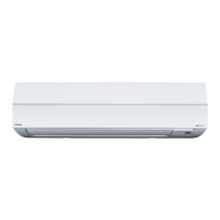
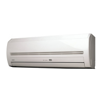
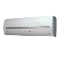
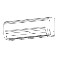
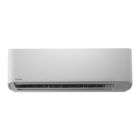
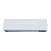
Provides detailed external views and dimensions of the indoor unit for model identification.
Presents the electrical schematic for the indoor unit, showing component connections.
Details specifications for major indoor unit parts.
Labels and describes the external parts of the indoor unit.
Explains the various indicators and symbols on the remote controller display.
Details the functions of each button on the remote controller for operation and setup.
Outlines initial setup steps and requirements before first-time operation.
Explains how to start, stop, select modes, adjust air volume, and set temperature.
Provides guidelines for adjusting louvers for optimal air direction.
Details the procedure for adjusting horizontal and vertical louvers.
Describes the three available timer operation types: OFF, Repeat OFF, and ON.
Provides step-by-step instructions for setting and canceling timer operations.
Details criteria for choosing an appropriate installation location.
Highlights critical safety precautions for electrical wiring installation.
Explains how to clean the air filters when indicated.
Provides instructions for cleaning the indoor unit and remote controller.
Lists essential checks to perform before operating the air conditioner.
Explains heating capacity, defrost operation, and protective measures.
Lists common symptoms for the outdoor unit and their potential causes.
Lists common symptoms for the indoor unit and their potential causes.
Explains how to access and interpret error codes stored in the remote controller's history.
Lists essential checks to perform before executing a test run.
Details the steps for performing test runs using wired and wireless remote controllers.
Explains how to confirm errors and access the error history on the remote controller.
Provides a detailed list of check codes, their meanings, and troubleshooting steps.
Outlines the function and connection details of key components in the refrigerating cycle.
Details specifications for power reset, mode selection, temperature control, and capacity control.
Explains how to set various functions for the indoor unit using a wired remote controller.
Details wiring and setup procedures for the remote location ON/OFF control box.
Explains how to operate the ventilating fan using the wired remote controller.
Provides the wiring diagram for ventilating fan control.
Defines the control items for the Leaving-ON prevention function.
Describes the steps for operating the Leaving-ON prevention control.
Details specifications for optional switches and connectors on the Wall-Type P.C. Board.
Summarizes common operational issues and their initial check items.
Outlines the systematic steps for troubleshooting when a problem occurs.
Provides a comprehensive list of check codes, their display locations, and judging devices.
Details the procedure for confirming and checking errors using the main remote controller.
Explains how to confirm error history using the TCC-LINK central control remote controller.
Lists check codes and their display positions on remote controllers and outdoor units.
Provides cautions and procedures for servicing the compressor and its related components.
Details checks for the external fan motor and inverter output.
Specific troubleshooting steps for low-pressure protection during cooling.
Specific troubleshooting steps for low-pressure protection during heating.
Procedure to check balance pipe valves and sensors for oil level detection issues.
Details procedures for checking leakage in SV3A and SV3C valves.
Explains how to check for clogging in SV3B and SV3E valves.
Procedure to check for clogging in the oil return circuit from the oil separator.
Procedure to check TK1 sensor installation, connection, and resistance.
Procedure to check TK2 sensor installation, connection, and resistance.
Procedure to check TK3 sensor installation, connection, and resistance.
Procedure to check TK4 sensor installation, connection, and resistance.
Troubleshooting for duplicated indoor header unit addresses.
Procedure for correcting duplicated outdoor line address setups.
Troubleshooting for duplicated priority settings among indoor units.
Procedure for addressing errors in group line connectivity for individual indoor units.
Procedure for setting indoor group and addresses when unset.
Steps to set indoor unit capacity when it is unset.
Procedure for setting outdoor unit capacity when it is unset.
Troubleshooting for duplicated central control addresses.
Procedure for addressing errors related to the quantity of connected outdoor units.
Details the diagnosis and correction steps for IPDU quantity errors.
Troubleshooting steps for AI-NET communication line errors.
Procedure for addressing Extended IC errors.
Troubleshooting steps for TD1 sensor errors, including valve and circuit checks.
Troubleshooting steps for high-pressure switch actuation during cooling.
Troubleshooting steps for high-pressure switch actuation during heating.
Details checks for fan motor rotation, voltage, and RPM.
Procedure to check PMV connectors, Pd/Ps sensor output, and balance pipe valves.
Troubleshooting for TS1 sensor errors, including valve and coil checks.
Procedure for checking TD1/TD2 sensor errors and SV4 valve circuits.
Troubleshooting steps for TD2 sensor errors, including valve coil and connection checks.
Procedure to check 4-way valve coil connections and sensor characteristics.
Troubleshooting steps for high-pressure protective operation during cooling.
Troubleshooting steps for high-pressure protective operation during heating.
Procedure to check fan IPDU, motor lock, and fixation.
Troubleshooting steps for G-Tr short-circuit errors related to power, IPDU, and compressor.
Procedure to check compressor connection, wiring, and grounding.
Troubleshooting steps for AI-NET communication line errors.
Procedure for addressing Extended IC errors.
Illustrates the block diagram for the indoor unit's control circuit.
Shows the block diagram of the indoor unit when connected with a wireless remote controller.
Provides crucial safety warnings and precautions before replacing parts.
Details the steps for removing the front panel of the indoor unit.
Explains the procedure for removing the electric parts assembly.
Details the steps for removing and replacing the PMV motor.
Explains how to remove the horizontal louver shaft.
Details the steps for removing the evaporator (heat exchanger).
Explains how to remove the bearing base and bearing.
Details the steps for removing the fan motor.
Provides instructions for correctly installing the cross flow fan and motor.
Outlines the procedure for replacing the indoor P.C. board, including data backup and restoration.
Details steps for replacing the P.C. board and powering on the unit.
Explains the method for setting DIP switches on the P.C. board.
Provides instructions for writing setup data into the EEPROM.
Provides an exploded view and a list of parts for the indoor unit.
Lists parts and their corresponding numbers for specific indoor unit models.
Lists parts and their corresponding numbers for specific indoor unit models.
Lists parts and their corresponding numbers for specific indoor unit models.