EasyManua.ls Logo

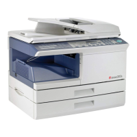
Toshiba e-STUDIO203S User Manual

Toshiba e-STUDIO203S
168 pages
To Next Page IconTo Next Page
Page #1 background imageLoading...
Page #1 background image
SERVICE MANUAL
MULTIFUNCTIONAL DIGITAL SYSTEMS
e-STUDIO203S
e-STUDIO203SD
Model: DP-2031/2032
Publish Date: July 2008
File No. SME080002A0
R080621G0500-TTEC
Ver01_2008-09

Table of Contents

Other manuals for Toshiba e-STUDIO203S

Questions and Answers:

Toshiba e-STUDIO203S Specifications

General IconGeneral
TypeDigital Copier
FunctionsPrint, Copy, Scan
Print Speed (Black)20 ppm
First Print Out Time (Black)8.5 seconds
Print Resolution600 x 600 dpi
Copy Speed20 cpm
Copy Resolution600 x 600 dpi
Scan Resolution600 x 600 dpi
Scan Speed20 ipm
Paper Capacity250 sheets
Zoom25% to 400%
InterfaceUSB 2.0
Paper SizeA4, A5, Legal, Letter
Paper Weight64 - 163 g/m² (Cassette)

Summary

Trademarks

General Precautions for Installation and Service

1. Transportation and Installation

Guidance on safe transportation and installation practices for the machine.

2. Machine Servicing Precautions

Safety guidelines and precautions to observe during machine servicing.

3. Key Safety Parts Handling

Identification and proper handling of critical safety components for service.

4. Cautionary Labels Check

Checking the condition and placement of important cautionary labels on the machine.

5. Consumable and Packing Material Disposal

Following regulations for disposal of consumables and packing materials.

6. Static Electricity Precautions

Guidelines for handling PC boards to prevent damage from static electricity.

Laser Safety Precautions

Laser Optical Unit Replacement

Exchange the entire laser optical unit, not individual parts, when a problem occurs.

Avoid Laser Beam Exposure

Do not look into the machine or laser beam exposure slit during servicing.

Safety Interlock Switch

Do not defeat the safety interlock by inserting wedges or other items.

General Product Safety

Laser Safety Warning

Do not remove covers or access the product interior; refer servicing to qualified personnel.

[1] GENERAL

1. Major functions

Overview of the configurations and major functions of the machine.

2. Note for servicing and handling

Important notes and countermeasures for servicing and handling the machine.

[2] SPECIFICATIONS

1. Basic specifications

Details on physical dimensions, weight, and basic operational parameters.

2. Operation specifications

Specifications related to paper feed, scanning, image forming, and developing systems.

[3] CONSUMABLE PARTS

1. Supply list

List of consumable parts, including names, quantities, and packing forms.

2. Environmental

Environmental conditions required for optimal copy quality and machine operation.

3. Production control number (lot No.) identification

Explanation of how to identify production control numbers on toner and drum cartridges.

4. Toner cartridge replacement

Step-by-step instructions for safely replacing the toner cartridge.

[4] EXTERNAL VIEWS AND INTERNAL STRUCTURES

1. Appearance

Diagrams illustrating the external features and parts of the machine.

2. Internal

Diagrams showing the internal components and their locations.

3. Operation panel

Detailed description of each key and display element on the operation panel.

4. Motors, solenoids and clutch

Identification and function of motors, solenoids, and clutches within the machine.

5. Sensors and switches

Identification and function of various sensors and switches in the machine.

6. PWB unit

List and function of the Printed Wiring Board (PWB) units in the machine.

7. Cross sectional view

Diagram illustrating the internal layout and part functions in cross-section.

[5] UNPACKING AND INSTALLATION

1. Copier installation

Instructions for proper installation to prevent damage and ensure performance.

2. Cautions on handling

Precautions to maintain copier performance, avoiding shock and sunlight exposure.

3. Checking packed components and accessories

Procedure to verify all included components and accessories after unpacking.

4. Unpacking

Steps to unpack the machine and carry it to the installation location.

5. Removing protective packing materials

Detailed instructions for removing protective tapes and pins from the machine.

6. Developer unit installation

Step-by-step guide for installing the developer unit correctly.

7. Toner cartridge installation

Instructions for shaking and installing the toner cartridge properly.

8. Loading the paper tray

Guidance on properly fanning and loading paper into the paper tray.

9. Power to copier

Instructions for connecting the power cord and ensuring proper grounding.

10. Software

Information on the accompanying CD-ROM software and hardware requirements.

11. Interface

Details on the USB connector, cable, and pin configuration.

12. Moving

Instructions and precautions for moving the unit safely.

13. Scanner moisture-proof parts

Instructions for installing parts to alleviate dew condensation in humid environments.

[6] COPY PROCESS

1. Functional diagram

Diagram illustrating the basic operation cycle of the copy process.

2. Outline of print process

Explanation of the non-impact printer's process using semiconductor laser and OPC drum.

3. Actual print process

Detailed breakdown of the actual print process steps: DC charge, exposure, developing, transfer.

[7] OPERATIONAL DESCRIPTIONS

1. Outline of operation

Overview of the machine's basic configuration and operational flow.

2. Scanner section

Description of the scanner unit, optical system, and drive system.

3. Laser unit

Details on the laser unit's basic structure, beam path, and composition.

4. Fuser section

General description of the fuser section, including heat roller, separator pawls, and thermal control.

5. Paper feed section and paper transport section

Explanation of paper feeding methods and general operations.

6. RADF section

Description of the RADF's outline, document path, composition, and operational descriptions.

7. D-D (Duplex to Duplex) mode paper/document transport (Duplex model)

Explanation of paper and document transport for duplex copying modes.

8. Shifter

Description of the shifter's function, shift width, and offset operation.

[8] DISASSEMBLY AND ASSEMBLY

1. High voltage section

Procedures for disassembling and assembling the high voltage section.

2. Operation panel section

Steps for disassembling and assembling the operation panel unit and PWB.

3. Optical section

Procedures for disassembling and assembling the optical section components.

4. Fusing section

Detailed steps for disassembling and assembling the fusing section parts.

5. Tray paper feed/transport section

Procedures for disassembling and assembling the tray paper feed and transport mechanisms.

6. Manual paper feed section

Steps for disassembling and assembling the manual paper feed section.

7. Rear frame section

Procedures for disassembling and assembling the rear frame components.

8. Power section

Steps for disassembling and assembling the power supply section.

9. DV unit section

Procedures for disassembling and assembling the DV unit, including DV seal and blade.

10. Duplex motor section (e-STUDIO203SD only)

Steps for disassembling and assembling the duplex motor section.

11. Reverse roller section (e-STUDIO203SD only)

Procedures for disassembling and assembling the reverse roller section.

12. RADF section

Steps for disassembling and assembling the RADF section components.

[9] ADJUSTMENTS

1. Optical section

Procedures for adjusting copy magnification ratios in main and sub scanning directions.

2. Copy density adjustment

Guidelines and timing for adjusting copy density for optimal print quality.

3. High voltage adjustment

Procedures for adjusting main charger (grid bias) and checking DV bias.

4. Duplex adjustment

Adjusting paper reverse position for duplex copying and trailing edge void.

5. RADF scan position automatic adjustment

Procedure for automatically adjusting RADF scan position using test command 53-08.

6. RADF mode sub scanning direction magnification ratio adjustment

Adjusting the sub scanning direction magnification ratio for RADF documents.

7. Automatic black level correction

Procedure for automatic black level correction using a test chart.

[10] TEST COMMAND, TROUBLE CODES

1. Entering the test command mode

Instructions on how to access and cancel the test command mode.

2. Key rule

Explanation of key usage for navigating test commands and making adjustments.

3. List of test commands

Comprehensive list of main and sub codes for test commands and their functions.

4. Descriptions of various test commands

Detailed explanations of various test commands and their operational procedures.

[11] MAINTENANCE

1. Maintenance table

Table outlining maintenance checks, cleaning, adjustments, and lubrication for various parts.

2. Maintenance display system

Information on the maintenance display system for toner and developer status.

[12] USER PROGRAM

1. User programs

List and explanation of user settable programs for copy mode.

A. Copy mode

Detailed descriptions of available copy mode user programs and their settings.

B. Print mode

List of user settable programs related to printer functions.

2. Selecting a setting for a user program

Step-by-step instructions on how to select and change user program settings.

[13] ELECTRICAL SECTION

1. Block diagram

Overall block diagram illustrating the interconnections of the machine's electronic components.

A. Overall block diagram

Detailed block diagram showing major PWB units and their connections.

2. Signal name list

List of signal names, their functions, and the sections they relate to.

[14] CIRCUIT DIAGRAM

1. MCU PWB

Circuit diagram for the MCU PWB (CPU, ASIC, Driver, Memory sections).

2. OPERATION PWB

Circuit diagram for the Operation PWB (LED/LCD, KEY/Buzzer, Connector sections).

3. ACTUAL WIRING DIAGRAM

Wiring diagrams illustrating connections between major units like MCU PWB, RADF, and optional units.

[15] FIRMWARE DOWNLOAD PROCEDURES

1. Initial setting (Serial number setting procedures)

Procedure for setting the serial number on the PC for firmware downloading.

2. Download procedures

Step-by-step guide for downloading firmware to the main unit from a PC.

3. Version acquisition procedures

Procedure to acquire firmware version information from the machine to the PC.

4. EEPROM data acquisition procedure

Procedure to acquire EEPROM data from the machine to the PC for data maintenance.

5. Installing procedures

Instructions for installing the USB integration maintenance program and drivers on Windows.

LEAD-FREE SOLDER

(1) NOTE FOR THE USE OF LEAD-FREE SOLDER THREAD

Guidelines for using lead-free solder thread and soldering iron for PWB repair.

(2) NOTE FOR SOLDERING WORK

Precautions for soldering work due to lead-free solder's higher melting point and tin content.

CAUTION FOR BATTERY REPLACEMENT

CAUTION FOR BATTERY DISPOSAL

Related product manuals