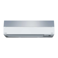
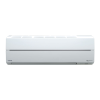
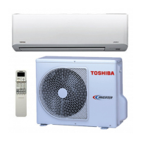
Do you have a question about the Toshiba RAS-10SKV2-E and is the answer not in the manual?
Important safety warnings and precautions for general users and during servicing.
Detailed specifications for RAS-10/13 models, including capacity, power, and dimensions.
Detailed specifications for RAS-16 models, including capacity, power, and dimensions.
Curves for operation characteristics and capacity variation based on temperature.
Covers R410A safety, piping, required tools, and refrigerant recharging procedures.
Details brazing filler materials, flux, and the brazing process to prevent oxidation.
Exploded views and dimensional details of indoor and outdoor unit components.
Wiring schematic for RAS-10SKV2-E, RAS-10SAV2-E, RAS-13SKV2-E, RAS-13SAV2-E.
Wiring schematic for RAS-16SKV2-E and RAS-16SAV2-E units.
List and specifications of electrical components for the indoor unit.
List and specifications of electrical components for the outdoor unit.
Diagram illustrating the refrigerant flow for RAS-10SKV2-E/RAS-10SAV2-E.
Diagram illustrating the refrigerant flow for RAS-13SKV2-E/RAS-13SAV2-E.
Diagram illustrating the refrigerant flow for RAS-16SKV2-E/RAS-16SAV2-E.
Provides key operating data for cooling and heating modes.
Diagram showing functions and control flow of the indoor unit's MCU.
Diagram illustrating the control logic and components of the outdoor unit inverter.
Overview of system control, roles of units, and signal communication.
Introduces various operation modes like basic, fan control, ECO, Quiet, and Hi-POWER.
Details how the remote controller, indoor, and outdoor units manage operation.
Explains fan speed control logic for cooling and heating operations.
Describes control of outdoor fan speed based on temperature and compressor speed.
Details the energy-saving ECO mode for cooling and heating operations.
Covers Quiet mode for reduced noise and Comfort Sleep mode for energy saving.
Details Hi-POWER mode and the function of the filter indicator.
Instructions for enabling, disabling, and managing the auto restart function.
Identifies buttons, explains basic operations, and details specific modes.
Explains the meaning of icons and indicators shown on the remote controller display.
Covers unit diagrams, optional parts, included accessories, and required tools for installation.
Covers unit placement, drilling, electrical work, wiring, and piping.
Covers unit placement, drainage, piping connection, wiring, and evacuation.
Includes gas leak testing, system test, auto restart, and remote controller settings.
Covers first confirmation, primary judgment, and LED fault diagnosis.
Methods for primary troubleshooting and interpreting indoor unit LED flashing codes.
Using the remote controller in service mode to retrieve check codes.
List of error codes and their corresponding causes and actions for diagnosis.
Troubleshooting steps for indoor unit issues like no power or remote control problems.
Diagnostic flow for when the indoor fan motor does not operate or rotates improperly.
Troubleshooting for indoor fan motor automatically rotating upon power supply activation.
Flowchart for diagnosing remote control issues related to signal transmission.
Diagnosing issues when the outdoor unit does not operate or stops shortly after starting.
Procedures for checking the pulse motor valve and performing basic system checks.
Flowchart for diagnosing inverter assembly, including fuse, capacitor, and motor checks.
Procedures for checking the indoor unit's main and indication P.C. boards for defects.
Diagram showing component layout and sensor characteristic tables for the indoor P.C. board.
Procedures for checking sensors, remote control, louver, and fan motor resistance.
Procedures for checking compressor, fan motor, valve coils, and sensors resistance.
Methods for checking electrolytic capacitors and converter modules for proper function.
Steps to diagnose if the outdoor fan motor is good or bad by checking resistance.
Detailed procedures for replacing indoor unit components like front panel, motor, and PCB.
Steps for removing and reassembling the front panel of the indoor unit.
Procedure for removing and replacing the electric parts box assembly.
Instructions for replacing the horizontal louver and evaporator (heat exchanger).
Procedures for replacing the bearing and fan motor.
Instructions for replacing the cross flow fan and microcomputer.
Procedure for detaching and attaching outdoor unit covers, cabinets, and cables.
Steps for replacing the front cabinet and inverter assembly.
Instructions for disconnecting connectors and replacing the control board assembly.
Procedures for replacing side cabinets and the fan motor.
Steps for replacing the compressor and reactor.
Instructions for replacing the electronic expansion valve coil and fan guard.
Procedures for installing TE, TS, TD, and TO sensors.
Detailed steps for replacing temperature sensors, including part details.
Exploded view and parts list for the indoor unit components.
Detailed list of parts for the indoor unit, including motors, filters, and controls.
Exploded view and parts list for the outdoor unit components.
| Type | Split System |
|---|---|
| Cooling Capacity | 2.5 kW |
| Heating Capacity | 3.2 kW |
| Power Supply | 220-240V, 50Hz |
| Refrigerant | R410A |
| Indoor Unit Dimensions (W x H x D) | 740 x 250 x 200 mm |
| Outdoor Unit Dimensions (W x H x D) | 660 x 530 x 240 mm |
| Weight (Indoor Unit) | 9 kg |
| Energy Efficiency Ratio (EER) | 3.21 |
| Coefficient of Performance (COP) | 3.61 |
| Noise Level (Outdoor Unit) | 50 dB(A) |


