Do you have a question about the Toshiba RAS-10SKH-E and is the answer not in the manual?
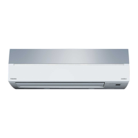
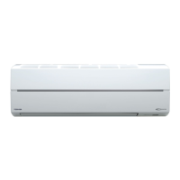
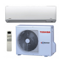
Visual representation and dimensions of the indoor unit.
Visual representation and dimensions of the outdoor unit.
List of electrical components for the indoor unit.
List of electrical components for the outdoor unit.
Process to melt ice from the outdoor unit during heating.
Feature for automatic restart after power interruption.
Critical safety guidelines and warnings for installation.
Visual guide for unit placement and connection points.
General steps and considerations for installation.
Specific instructions for installing the indoor unit.
Guidelines for electrical connections and power requirements.
Step-by-step instructions for connecting wires.
How to install refrigerant pipes and the drain hose.
Guidelines for selecting an installation location for the outdoor unit.
Detailed steps for connecting the refrigerant piping.
Procedure for evacuating air from the refrigerant circuit.
Instructions for making electrical connections to the outdoor unit.
Initial checks for basic operational problems.
Identifying the likely source of a malfunction.
Step-by-step flowcharts for diagnosing problems.
Methods for diagnosing remote control and PC board functionality.
| Type | Split System |
|---|---|
| Cooling Capacity | 2.5 kW |
| Heating Capacity | 3.2 kW |
| Power Supply | 220-240V, 50Hz |
| Refrigerant | R410A |
| Energy Efficiency Ratio (EER) | 3.21 |
| Coefficient of Performance (COP) | 3.61 |
| Outdoor Unit Dimensions (W x H x D) | 660 x 530 x 240 mm |
| Indoor Unit Weight | 9 kg |
| Noise Level (Outdoor) | 48 dB(A) |


