Do you have a question about the Toshiba RAS-10SKVR-E and is the answer not in the manual?
| Brand | Toshiba |
|---|---|
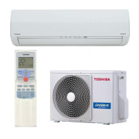
| Model | RAS-10SKVR-E |
| Category | Air Conditioner |
| Language | English |
Guidelines for power supply cord, servicing precautions, and unit maintenance safety.
Cautions regarding R410A refrigerant, impurity prevention, and special tool requirements.
Procedure for disconnecting power and warnings about high voltage circuits.
Warnings against combustible gas locations and placement near heat sources.
Warnings about modifying unit, weight bearing, grounding, and electrical work.
Detailed specifications for indoor and outdoor units, capacities, and electrical characteristics.
Graphs illustrating cooling and heating operation curves based on compressor speed.
Charts showing capacity variation based on outdoor temperature for cooling and heating.
Precautions for handling R410A refrigerant, tool usage, and leak prevention.
Specifications and requirements for copper pipes and joints used with R410A refrigerant.
Procedures for cutting, deburring, and flaring pipe materials for refrigerant lines.
Precautions for flare connections, tightening torque values, and oil application.
List of tools exclusive for R410A and their interchangeability with conventional tools.
Step-by-step guide for recharging refrigerant, including recovery, evacuation, and charging.
Instructions on handling refrigerant cylinders (with/without siphon) and charging liquid refrigerant.
Details on brazing filler materials, flux types, and their properties for pipe joining.
Guidelines for brazing materials, flux usage, and preventing oxidation with nitrogen gas.
Detailed diagrams showing dimensions and parts of the indoor unit models.
Detailed diagrams showing dimensions and parts of indoor unit models RAS-13SKV-E and RAS-16SKV-E.
Diagrams illustrating the dimensions and installation clearances for the outdoor unit.
Schematic wiring diagram for the RAS-10SKVR-E/RAS-10SAVR-E and RAS-13SKVR-E/RAS-13SAVR-E models.
Schematic wiring diagram for the RAS-16SKV-E/RAS-16SAV-E and RAS-16SKVR-E/RAS-16SAVR-E models.
List of electrical components for the indoor unit with their model names and specifications.
List of electrical components for the outdoor unit with their model names and specifications.
Diagram illustrating the refrigerant flow and components for RAS-10/13 models.
Diagram illustrating the refrigerant flow and components for RAS-13/16 models.
Diagram illustrating the refrigerant flow and components for RAS-16 models.
Table showing operation data for cooling and heating modes, including pressure and temperature.
Block diagram showing the control flow and components of the indoor unit and remote controller.
Control block diagram for the RAS-16SKV-E indoor unit, detailing MCU functions and remote controller interface.
Control block diagram for RAS-10SKVR-E and RAS-13SKVR-E indoor units, including air purifier.
Control block diagram for the RAS-16SKVR-E indoor unit, showing MCU functions and remote controller interface.
Block diagram of the outdoor unit's microcomputer, detailing its functions and connections.
Overview of the capacity-variable system, indoor/outdoor unit control, and compressor control.
Functions and responsibilities of the indoor and outdoor unit controllers in managing operations.
Details of serial signals exchanged between indoor and outdoor units for operation commands.
Descriptions of various operations like basic, cooling/heating, AUTO, DRY, fan motor control, and filter indicator.
Flowchart detailing the basic operation control, remote controller functions, and unit control.
Explanation of cooling/heating, AUTO, and DRY operation modes, including temperature controls.
Details on controlling indoor fan speed in cooling mode, including manual and AUTO settings.
Details on controlling indoor fan speed in heating mode, including cold draft prevention.
Control logic for the outdoor fan motor based on temperature, compressor speed, and operation mode.
Explanation of capacity adjustment by compressor revolution and current release protection.
Description of protective control based on indoor heat exchanger temperature for cooling and heating.
Procedure and conditions for defrost operation in heating mode, including zone detection.
Details on louver position control, air direction adjustment, and swing operation.
Explanation of the ECO operation mode for energy saving in cooling and heating.
How to perform temporary operation and control the air purifying function.
Detection methods for abnormalities in the air purifying function, indicated by the FILTER indicator.
Control operation for compressor speed based on discharge temperature to prevent errors.
Function of the P.M.V. in controlling refrigerant flow and its operation during various modes.
Purpose and operation of the self-cleaning function to maintain indoor unit cleanliness.
Diagram of self-cleaning operation and procedures to cancel or set the function.
Procedure for selecting remote control mode (A or B) when two units are installed nearby.
Explanation of Quiet mode for reduced noise and Comfort Sleep mode for energy saving.
Purpose and setting of the short timer for testing and trial operations.
Description of One-Touch Comfort and Hi-POWER modes for automated and enhanced operation.
Explanation of the FILTER indicator for air purifier maintenance and how to turn it off.
Procedure for setting the auto restart function to resume operation after power failure.
Steps to cancel auto restart and how power failure affects timer operations.
Identification and basic functions of buttons on the remote controller.
How to use One-Touch and Automatic operation modes via the remote controller.
Instructions for selecting cooling, heating, or fan-only operation and setting temperature/fan speed.
Details on Dry mode for dehumidification and Air Purifying operation with plasma ionizer.
Explanation of Hi-POWER, ECO for energy saving, and Temporary Operation.
Procedures for setting ON/OFF timers and everyday timers for automated operation.
How to set preferred operations for future use and manage auto restart functionality.
Details on Quiet mode for low noise and Comfort Sleep mode for energy saving during sleep.
How to set the sleep timer for automatic OFF operation.
Explanation of various indicators and functions displayed on the remote controller.
Safety precautions to be followed before installing the wireless remote controller and the unit.
List of optional parts, accessories, and installation parts included with the unit.
Information on new tools required for R410A installation and changes from R22 models.
Guidelines for selecting an appropriate installation place for the indoor unit.
Procedure for drilling holes and mounting the installation plate for the indoor unit.
Steps for securely mounting the installation plate and performing electrical work.
Step-by-step instructions for connecting the indoor unit's wiring cable.
Instructions for forming piping and installing the drain hose, including insulation.
Procedure for attaching the drain cap and drain hose correctly to prevent leaks.
Guidelines for connecting pipes and recommended bending radius for proper installation.
Instructions for binding pipes, arranging them, and ensuring proper drain hose installation.
Guidelines for selecting a suitable installation location for the outdoor unit and precautions.
Guidelines for accurately adding refrigerant using a scale and liquid form.
Procedure for draining water from the outdoor unit and connecting refrigerant pipes.
Instructions for tightening flare connections and using a vacuum pump for evacuation.
Precautions for packed valve handling and connecting the power cord and cable.
Steps for performing a gas leak test and system test operation.
How to set Auto Restart and select remote controller mode (A/B).
Overview of troubleshooting steps, including initial confirmation, primary judgment, and LED diagnostics.
Safety warnings and precautions when handling the new inverter (3DV Inverter) and its circuitry.
Safety measures for inspecting the outdoor unit's control section, especially concerning high voltage.
Steps for confirming power supply, voltage, and identifying normal program operations.
Methods for primary judgment and interpreting self-diagnosis codes from indoor unit flashing LEDs.
Procedure for initiating self-diagnosis via the remote controller to retrieve check codes.
Table correlating block distinctions and check codes with causes of operation failure.
Table detailing block distinctions, causes, and recommended actions for troubleshooting.
Flowchart for diagnosing 'Power is not turned on' issues in the indoor unit.
Confirmation procedure for indoor unit power issues after replacing the P.C. board.
Flowchart for diagnosing issues when only the indoor fan motor does not operate in cooling.
Troubleshooting steps for indoor fan motor operation, applicable to RAS-16 Series.
Diagnosing why the indoor fan motor automatically rotates on power supply for DC fan models.
Diagnosing why the indoor fan motor automatically rotates on power supply for AC fan models.
Flowchart for diagnosing problems with the remote controller, including signal transmission.
Diagnosing wiring failures related to the outdoor unit not operating or stopping intermittently.
Procedure for diagnosing check codes 1C (miswiring) and 1E (gas leakage, discharge temp error).
Steps to check the functionality of the air purifier and its components.
Steps to check the functionality of the minus ion generator and its high-voltage output.
Flowchart for diagnosing issues with the outdoor unit's inverter assembly, including fan motor and compressor.
Procedures for checking the indoor unit's P.C. board, including operating precautions.
Detailed check procedures for indoor unit issues, including power supply and motor checks.
Detailed check procedures for indoor unit issues, including power supply and motor checks for RAS-16 Series.
Layout of the P.C. board for RAS-10,13 Series and sensor resistance characteristics.
Layout of the P.C. board for RAS-16 Series and sensor resistance characteristics.
Procedures for checking indoor unit parts like sensors, remote controller, and fan motors.
Procedures for checking outdoor unit components like compressor, fan motor, and sensors.
Methods for checking electrolytic capacitors and diode blocks for proper functionality.
Steps to determine if the outdoor fan motor is good or bad based on resistance and rotation.
Procedure for removing and replacing the front panel of the indoor unit.
Instructions for reassembling the front panel, including plasma air purifier installation.
Procedure for removing and replacing the high voltage generator and air ionizer.
Procedure for removing and replacing the electric parts box assembly and its components.
Steps for replacing the horizontal louver and the evaporator (heat exchanger).
Procedure for removing and replacing the fan motor bearing and its base.
Steps for removing and replacing the fan motor, including motor cover and band.
Precautions and procedures for reassembling the cross flow fan and fan motor.
Procedure for replacing the microcomputer P.C. board for RAS-10,13 Series.
Layout of the P.C. board for RAS-16 Series, showing component locations.
Procedure for attaching the waterproof cover and upper cabinet of the outdoor unit.
Procedure for removing and attaching the front cabinet of the outdoor unit.
Procedure for checking and replacing the inverter assembly, including capacitor discharging.
Procedure for disconnecting and replacing the control board assembly and heat sink.
Procedure for removing and attaching the right and left side cabinets of the outdoor unit.
Procedure for replacing the fan motor and propeller, including flange nut tightening.
Procedure for replacing the compressor and reactor, including pipe disconnection and tightening.
Procedure for replacing the electronic expansion valve coil and fan guard.
Instructions for attaching and replacing temperature sensors (TE, TS, TD, TO) with cautions.
Detailed method for replacing temperature sensors and list of required service parts.
Exploded view and part number list for the indoor unit components.
Exploded view and part number list for additional indoor unit components.
Exploded view illustrating the components of the outdoor unit.
List of part numbers and descriptions for the outdoor unit components.
Layout of the P.C. board and list of associated parts.