EasyManua.ls Logo

Toshiba RAS-13G2KVP-E User Manual

Toshiba RAS-13G2KVP-E
127 pages
To Next Page IconTo Next Page
Page #1 background imageLoading...
Page #1 background image
R410A
SERVICE MANUAL
SPLIT TYPE
Indoor Unit Outdoor Unit
<High Wall, Heat Pump Type> <Heat Pump Type>
RAS-13G2KVP-E / RAS-13G2AVP-E
May, 2014
FILE NO. SVM-14017
RAS-10G2KVP-E / RAS-10G2AVP-E
RAS-16G2KVP-E / RAS-16G2AVP-E

Table of Contents

Question and Answer IconNeed help?

Do you have a question about the Toshiba RAS-13G2KVP-E and is the answer not in the manual?

Toshiba RAS-13G2KVP-E Specifications

General IconGeneral
TypeSplit System
Cooling Capacity3.5 kW
Heating Capacity4.0 kW
Power Supply220-240V, 50Hz
RefrigerantR410A
Indoor Unit Weight9 kg
Noise Level (Outdoor)50 dB(A)

Summary

1. SAFETY PRECAUTIONS

New refrigerant air conditioner installation

Precautions for installing air conditioners using new HFC refrigerant.

DANGER

Electrical Shock Hazard

Warnings about electrical shock risks during installation and servicing.

CAUTION

Equipment Damage Hazard

Cautions regarding potential equipment damage from improper installation or use.

2. SPECIFICATIONS

3. REFRIGERANT R410A

3-1. Safety During Installation/Servicing

Safety precautions for handling R410A refrigerant during installation and servicing.

3-2. Refrigerant Piping Installation

Guidelines for installing refrigerant piping using appropriate materials and joints.

3-3. Tools

3-3-1. Required Tools

Lists tools specifically required for R410A installation and interchangeability.

3-4. Recharging of Refrigerant

3-5. Brazing of Pipes

3-5-1. Materials for Brazing

Describes different types of brazing filler materials used for pipe joining.

3-5-3. Brazing

4. CONSTRUCTION VIEWS

4-1. Indoor Unit

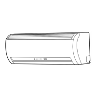
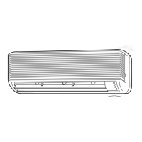
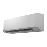
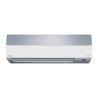
Provides diagrams and dimensions for the indoor unit's construction and installation.

4-2. Outdoor Unit

5. WIRING DIAGRAM

6. SPECIFICATIONS OF ELECTRICAL PARTS

6-1. Indoor Unit

Lists electrical parts and their specifications for the indoor unit.

6-2. Outdoor Unit

Lists electrical parts and their specifications for the outdoor unit.

7. REFRIGERANT CYCLE DIAGRAM

7-1. Refrigerant Cycle Diagram

Illustrates the refrigerant flow and components in the air conditioning system.

7-2. Operation Data

8. CONTROL BLOCK DIAGRAM

8-1. Indoor Unit

Shows the control block diagram for the indoor unit's functions and components.

8-2. Outdoor Unit (Inverter Assembly)

9. OPERATION DESCRIPTION

9-1. Outline of Air Conditioner Control

Provides an overview of the air conditioner's control system and its main functions.

9-2. Operation Description

1. Basic operation

Describes the fundamental operation control of the air conditioner.

7. Defrost control (Only in heating operation)

Function to remove frost from the outdoor heat exchanger.

8. Louver control

Controls the direction of air flow from the indoor unit.

21. POWER Selection Mode

Limits maximum current/power consumption to save energy and extend compressor life.

9-3. Auto Restart Function

9-3-1. How to Set the Auto Restart Function

Step-by-step instructions to enable the auto restart function after power failure.

9-4. Remote control

9-4-1. Remote control and its functions

Identifies and describes the functions of buttons and indicators on the remote controller.

9-4-2. Operation of remote control

Explains how to operate the remote control, including weekly timer settings.

10. INSTALLATION PROCEDURE

10-1. Installation Diagram of Indoor and Outdoor Units

Illustrates the required clearances and mounting positions for indoor and outdoor units.

10-2. Installation

10-2-1. Optional installation parts

Lists optional parts required for installation, such as pipes and insulating material.

10-2-2. Accessory and installation parts

Lists all accessories and installation parts included with the unit.

10-2-3. Installation/Servicing Tools

Highlights changes in components and necessary new tools for R410A systems.

10-3. Indoor Unit

10-3-1. Installation Place

Specifies suitable locations for installing the indoor unit, considering space and environment.

10-3-3. Piping and Drain Hose Installation

Piping and drain hose forming

Instructions on how to route and insulate refrigerant pipes and drain hoses.

10-3-4. Indoor Unit Fixing

10-3-5. In case of Indoor unit is fixed to Installation plate with screws

10-3-6. Drainage

10-4. Outdoor Unit

10-4-1. Installation Place

Specifies suitable locations for installing the outdoor unit, considering space, wind, and environment.

10-4-3. Draining the Water

10-4-4. Refrigerant Piping Connection

Flaring

Details the flaring process for refrigerant pipes, including dimensions and tools.

10-4-5. Evacuating

10-5. Electrical works

10-5-1. Wiring Connection

Provides instructions for connecting power supply and control cables to indoor and outdoor units.

10-5-2. Power Supply and Connecting Cable Connection

10-5-3. Power Supply input Wiring Diagram

10-6. Others

10-6-1. Gas leak test

Describes procedures for checking refrigerant gas leaks using detectors or soap water.

10-6-4. Auto restart setting

Instructions on enabling and disabling the auto restart function after power failure.

11. HOW TO DIAGNOSE THE TROUBLE

Precautions when handling the new inverter

Safety warnings and precautions when working with the new inverter, including high voltage.

Precautions when inspecting the control section of the outdoor unit

11-1. First Confirmation

11-1-1. Confirmation of Power Supply

Verifies that the power breaker operates correctly.

11-1-2. Confirmation of Power Voltage

Checks if the power voltage is within the acceptable range for normal operation.

11-1-3. Operation Which is not a Trouble (Program Operation)

Identifies normal operations that might be mistaken for malfunctions.

11-2. Primary Judgment

11-3. Judgment by Flashing LED of Indoor Unit

11-4. Self-Diagnosis by Remote Controller (Check Code)

11-4-1. How to Use Remote Controller in Service Mode

Instructions for accessing and using the remote controller's service mode for diagnosis.

11-5. Judgement of Trouble by Every Symptom

11-5-1. Indoor unit (Including remote controller)

Troubleshooting steps for indoor unit issues and remote controller problems.

11-5-2. Wiring Failure (Interconnecting and Serial Signal Wire)

(1) Outdoor unit does not operate

Diagnosing why the outdoor unit does not operate due to wiring issues.

(2) Outdoor unit stops in a little while after operation started

Troubleshooting steps when the outdoor unit stops shortly after starting.

11-6. Check Code 1C (Miswiring in indoor/outdoor units) and 1E

11-7. How to Diagnose Trouble in Outdoor Unit

11-8. Troubleshooting

11-8-1. How to Check Whether the Air Purifier and Minus Ion Gerneration are Good or NG

Method to check the functionality of the air purifier and ion generator.

11-9. How to Check Simply the Main Parts

11-9-1. How to check the P.C. board (Indoor unit)

Steps for checking the condition and functionality of the indoor unit's PC board.

11-9-2. How to shorten time for start the compressor.

Procedure to reduce the compressor waiting time during operation.

11-9-2. P .C . Board Layout

11-9-3. Indoor Unit (Other Parts)

11-9-4. Outdoor Unit

11-9-5. Checking Method for Each Part

11-10. How to Simply Judge Whether Outdoor Fan Motor is Good or Bad

12. HOW TO REPLACE THE MAIN PARTS

12-1. Indoor Unit

Detailed instructions for disassembling and replacing main parts of the indoor unit.

12-3. Outdoor Unit

13. EXPLODED VIEWS AND PARTS LIST

13-1. Indoor Unit

Provides exploded views and a parts list for the indoor unit components.

13-2. Indoor Unit (E-Parts Assy)

13-3. Outdoor Unit

13-4. P.C. Board Layout

Related product manuals