Do you have a question about the Toshiba RAS-13JAVP-E and is the answer not in the manual?
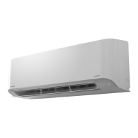
Details unit models for indoor and outdoor components.
Specifies electrical power requirements.
Lists performance coefficients for cooling and heating.
Provides noise levels for different modes.
Details dimensions and specifications of the indoor unit.
Details dimensions and specifications of the outdoor unit.
Specifies piping types and dimensions.
Details refrigerant type and weight.
Lists accessory items and connection types.
Lists included accessories for indoor and outdoor units.
Outlines safety precautions for handling R410A refrigerant.
Details requirements for installing refrigerant piping.
Lists tools required for R410A installation and general tools.
Details the step-by-step procedure for recharging refrigerant.
Describes different types of brazing filler materials.
Explains the purpose and types of flux used in brazing.
Provides construction diagrams and dimensions for the indoor unit.
Shows the wiring diagram for the indoor unit.
Lists specifications for indoor unit electrical parts.
Lists specifications for outdoor unit electrical parts.
Illustrates the refrigerant flow within the system.
Shows the control block diagram for the indoor unit.
Provides an overview of the air conditioner's control system.
Describes basic operation flow and control.
Explains control of the indoor fan motor in cooling operation.
Details control logic for the outdoor fan motor.
Explains how cooling/heating capacity is adjusted.
Describes function to prevent electronic part damage.
Details protective control based on indoor heat exchanger temperature.
Explains function to speed up heating operation in low temperatures.
Describes the defrost operation for the outdoor heat exchanger.
Details how louver position is controlled in cooling and heating.
Explains how to adjust air direction using the louver.
Describes the swing operation of the louvers.
Explains the quiet and mild operation mode.
Describes forced operation for tasks like refrigerant recovery.
Details the air filtering function and abnormal filter detection.
Explains how discharge temperature is controlled.
Details control of the refrigerant throttle amount via PMV.
Explains how to select between indoor units with multiple remotes.
Describes temporary auto and cooling operations using the reset button.
Explains the automatic restart function after power failure.
Details the filter check lamp and how to turn it off.
Identifies and explains the parts of the remote controller.
Provides essential safety precautions for installation.
Shows diagrams for installing indoor and outdoor units.
Lists optional parts for installation.
Lists standard accessories and installation parts.
Details new tools required for R410A installation.
Specifies suitable locations for installing the indoor unit.
Describes how to cut holes and mount the installation plate.
Details electrical wiring requirements and procedures.
Explains how to connect the indoor unit's wiring.
Covers installation of piping and drain hoses.
Details the process of hanging and installing the indoor unit.
Explains how to install the drain hose for proper drainage.
Specifies suitable locations for installing the outdoor unit.
Details how to connect refrigerant pipes.
Describes the process of evacuating air from the system.
Explains how to connect the outdoor unit's wiring.
Details how to perform a gas leak test.
Describes how to perform a test operation after installation.
Explains how to set the auto restart function.
Outlines initial checks for troubleshooting.
Describes primary methods for diagnosing troubles.
Explains how to diagnose issues based on LED flashing patterns.
Details self-diagnosis using the remote controller and check codes.
Guides on accessing and using the remote controller's service mode.
Provides cautions for servicing operations.
Guides judgment of indoor unit troubles, including remote controller issues.
Addresses troubleshooting for wiring failures between units.
Details troubleshooting for specific error codes related to wiring and sensors.
Provides general troubleshooting procedures.
Provides procedures to check the air filter's condition.
Guides checking the functionality of the minus ion generator.
Details how to diagnose trouble in the outdoor unit.
Summarizes troubleshooting steps for the inverter assembly.
Provides methods to check main parts of the unit.
Details methods for checking the indoor unit's P.C. board.
Shows the layout of components on the P.C. board.
Provides checking procedures for other indoor unit parts.
Provides checking procedures for outdoor unit components.
Details checking methods for specific electronic parts.
Guides on checking the outdoor fan motor's condition.
Details procedures for replacing main parts of the indoor unit.
Explains how to replace the electric dust collector unit.
Details procedures for replacing the microcomputer assembly.
Details replacement procedures for the outdoor unit.
Outlines common detachment and attachment procedures for the outdoor unit.
Details replacement of the front cabinet for the outdoor unit.
Details replacement procedures for the inverter assembly.
Details replacement of the control board assembly.
Details replacement procedures for the rear cabinet.
Guides replacement of temperature sensors for servicing purposes.
Provides exploded views and parts list for the indoor unit.
| Type | Split System |
|---|---|
| Cooling Capacity | 3.5 kW |
| Heating Capacity | 4.0 kW |
| Energy Efficiency Ratio (EER) | 3.21 |
| Power Supply | 220-240V, 50Hz |
| Refrigerant | R410A |
| Weight (Indoor Unit) | 9 kg |
| Outdoor Unit Noise Level | 50 dB(A) |
| Dimensions (Outdoor Unit) | 780 x 550 x 290 mm |