Do you have a question about the Toshiba RAS-13SAV2-E and is the answer not in the manual?
| Type | Split System |
|---|---|
| Cooling Capacity | 3.5 kW |
| Heating Capacity | 4.0 kW |
| Energy Efficiency Ratio (EER) | 3.21 |
| Power Supply | 220-240V, 50Hz |
| Refrigerant | R410A |
| Outdoor Unit Noise Level | 50 dB(A) |
| Coefficient of Performance (COP) | 3.61 |
| Indoor Unit Dimensions (WxHxD) | 798 x 293 x 230 mm |
| Outdoor Unit Dimensions (WxHxD) | 780 x 550 x 290 mm |
| Indoor Unit Weight | 9 kg |
| Outdoor Unit Weight | 31 kg |
Ensures safe practices during air conditioner installation and servicing procedures.
Details technical specifications for indoor and outdoor units.
Illustrates cooling and heating performance curves based on compressor speed.
Highlights critical safety precautions for R410A refrigerant handling.
Covers guidelines for selecting and installing appropriate piping materials and joints.
Lists essential tools for R410A installation and their specifications.
Details the types of brazing fillers and their applications for pipe connections.
Explains the necessity and types of flux for proper brazing operations.
Describes the technique using nitrogen gas to prevent oxidation during brazing.
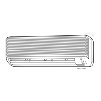
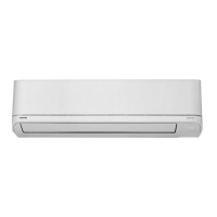
Provides detailed diagrams and dimensions of the indoor unit components.
Illustrates the construction and dimensions of the outdoor unit and its parts.
Schematic showing electrical connections for specific indoor and outdoor unit models.
Schematic illustrating electrical connections for specific indoor and outdoor unit models.
Lists the specifications for various electrical components within the indoor unit.
Details the specifications for electrical components in the outdoor unit.
Illustrates the refrigerant flow path for specific indoor and outdoor unit models.
Depicts the refrigerant flow path for specific indoor and outdoor unit models.
Shows the control logic and interconnections within the indoor unit.
Illustrates the control functions and components of the outdoor unit's inverter assembly.
Explains the overall control system architecture and functionality of the air conditioner.
Details various operational modes and functions of the air conditioner.
Describes how to set and manage the auto restart function after power interruptions.
Explains the functions and usage of the remote controller for operating the unit.
Details the indicators and controls on the indoor unit's operation panel.
Procedure for selecting remote control modes A or B for multi-unit installations.
Guide on how to adjust the brightness level of the indoor unit's display panel.
Visual guide illustrating the placement and clearances for indoor and outdoor unit installation.
Lists optional parts, accessories, and tools required for installation.
Provides detailed instructions for installing the indoor unit, including mounting.
Details the procedures and considerations for installing the outdoor unit.
Covers miscellaneous installation tasks like gas leak tests and remote control setup.
Highlights safety precautions when handling the inverter assembly due to high voltage.
Explains how to interpret LED flashing patterns for diagnosing indoor unit issues.
Guide on using the remote controller for performing self-diagnosis and retrieving check codes.
Troubleshooting steps for diagnosing issues when the indoor unit does not power on.
Step-by-step instructions for safely removing and replacing the front panel.
Procedure for accessing and replacing the electrical parts box (E-box).
Detailed steps for removing and replacing the compressor unit.
Lists all parts and their corresponding numbers for the indoor unit.
Provides a comprehensive list of parts and their numbers for the outdoor unit.
Diagrams showing the layout of components on the Printed Circuit Board.