EasyManua.ls Logo

Toshiba RAS-13UKHP-E4 - Control Block Diagram; 6-1. RAS-13 UKHP-E4; RAS-13 UAH-E4, RAS-10 UKHP-E4; RAS-10 UAH-E4, RAS-07 UKHP-E4; RAS-07 UAH-E4; 6-2. RAS-13 UKP-E4; RAS-13 UA-E4, RAS-10 UKP-E4; RAS-10 UA-E4, RAS-07 UKP-E4; RAS-07 UA-E4, RAS-13 UKPX4; RAS-13 UAX4, RAS-10 UKPX4; RAS-10 UAX4, RAS-07 UKPX4; RAS-07 UAX4, RAS-12 UKPX4; RAS-12 UAX4

Toshiba RAS-13UKHP-E4
93 pages
To Next Page IconTo Next Page
To Previous Page IconTo Previous Page
Loading...
8
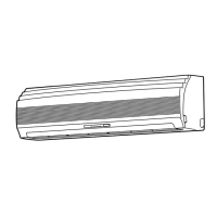
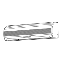
2. CONSTRUCTION VIEWS
2-1. Indoor Unit
Knock out system
Back body
Front panel
Air outlet
Air inlet
Air filter
Heat exchanger
Knock out system
66
0
275
790
208
48
48
48
26
4519040
32
64
590
320
620
235
235
215
215
9090
275
45
150150 160
160
120 80
53
66
0
Hanger
Hanger
Hanger
Hanger
Hanger
Drain hose (0.54 m)
Connecting pipe (0.43 m)
(Flare
6.35)
For stud bolt
(
8
~
10)
For stud bolt (
6)
Installation plate outline
Center line
Minimum
distance
to ceiling
170 or mor
e
Minimum
distance
to ceiling
170 or more
6
5 or
more
Minimum
distance
to ceiling
Wireless remote control
57
18
160
(For 13 series ; Flare
12.7
For 07,10 series ; Flare
9.52)
Connecting pipe (0.33 m)
FILE NO. SVM-05001

Table of Contents

Related product manuals