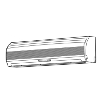
Do you have a question about the Toshiba RAS-13UKPX-T2 and is the answer not in the manual?
| Brand | Toshiba |
|---|---|
| Model | RAS-13UKPX-T2 |
| Category | Air Conditioner |
| Language | English |
Illustrates the refrigerant flow and operational parameters for this model combination.
Illustrates the refrigerant flow and operational parameters for this model combination.
Illustrates the refrigerant flow and operational parameters for this model combination.
Illustrates the refrigerant flow and operational parameters for this model combination.
Illustrates the refrigerant flow and operational parameters for this model combination.
Lists critical safety warnings and precautions for installation personnel.
Details the installation process specifically for the indoor unit.
Specifies suitable locations for indoor unit installation based on clearance and access.
Guidelines for connecting the indoor unit to the power supply.
Details the installation process specifically for the outdoor unit.
Specifies suitable locations for outdoor unit installation considering noise and environment.
Instructions for correctly connecting the refrigerant pipes using flare connections.
Steps for removing air and moisture from refrigerant lines using a vacuum pump.
Outlines the general approach to troubleshooting issues with the air conditioner.
Covers fundamental checks like power supply, cable connections, and program control.
Explains how to use the remote control's service mode for fault code retrieval.
Detailed step-by-step flowcharts for diagnosing specific operational failures.


