Do you have a question about the Toshiba RAS-18NKHP-E and is the answer not in the manual?
Electrical schematic for RAS-18NKHP-E and RAS-18NAH-E models.
Electrical schematic for RAS-24NKP-E, RAS-24NA-E, RAS-24NKPX, RAS-24N2AX.
Electrical schematic for RAS-18NKP-E, RAS-18NA-E, RAS-18NKPX, RAS-18N2AX.
Schematic of refrigerant flow and components for RAS-18NKHP-E/RAS-18NAH-E.
Refrigerant flow diagram for RAS-24NKP-E, RAS-24NA-E, RAS-24NKPX, RAS-24N2AX.
Refrigerant circuit diagram for RAS-18NKP-E and RAS-18NA-E models.
Essential safety warnings and precautions to be followed during installation.
Guide for selecting installation place, cutting holes, and mounting the indoor unit.
Instructions for selecting the outdoor unit place and connecting refrigerant piping.
General steps for diagnosing and troubleshooting air conditioner issues.
Essential initial checks for power, wiring, and program control.
Interpreting indicator lamps and performing initial fault diagnosis based on symptoms.
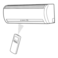
Using the remote control for self-diagnosis and interpreting error codes.
Flowcharts to diagnose specific faulty components based on error symptoms.
Specific troubleshooting for indoor unit issues like no power or fan failure.
| Brand | Toshiba |
|---|---|
| Model | RAS-18NKHP-E |
| Category | Air Conditioner |
| Language | English |