Do you have a question about the Toshiba RAS-18N3KV-E and is the answer not in the manual?
Detailed technical specifications for indoor and outdoor units, including capacity, power, and dimensions.
Safety precautions for R410A refrigerant during installation and servicing.
Guidelines for installing refrigerant piping using specific materials and joints.
Lists tools necessary for R410A installation and general tools.
Exploded views and dimensional details for indoor and outdoor units.
Wiring diagram illustrating connections between indoor and outdoor units.
Diagram illustrating the refrigerant flow path within the air conditioning system.
Block diagram of the indoor unit's control system and functions.
Block diagram of the outdoor unit's control system, including inverter assembly.
Overview of the air conditioner's control structure and component roles.
Detailed descriptions of various operating modes and functions.
Explanation of the automatic restart feature after power failure.
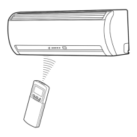
Information on the remote controller, its functions, and display indicators.
Illustrates the spatial arrangement and placement for indoor and outdoor unit installation.
Procedures for installing the indoor unit, including placement and mounting.
Guidelines for selecting an installation location for the outdoor unit.
Includes gas leak testing and remote control A-B selection procedures.
Initial checks for power supply and interpreting indoor unit LED indicators for diagnosis.
Using remote controller and symptom-based steps for fault finding.
Guides for diagnosing outdoor unit issues and checking main parts.
Detailed instructions for disassembling and replacing main parts of the indoor unit.
Procedures for detaching and attaching main parts of the outdoor unit.
Exploded view and parts list for the indoor unit's electrical components.
Exploded view and parts list for the main structural and functional parts of the indoor unit.
Exploded view and parts list for the main components of the outdoor unit.
Diagram showing the layout of the P.C. board in the outdoor unit.
| Brand | Toshiba |
|---|---|
| Model | RAS-18N3KV-E |
| Category | Air Conditioner |
| Language | English |