Do you have a question about the Toshiba RAS-24NAH-E and is the answer not in the manual?
Detailed specifications for various air conditioner models, including electrical and physical data.
Continued detailed specifications for various air conditioner models, covering electrical and physical data.
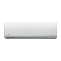
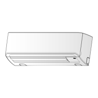
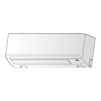
Visual representation of the indoor unit's physical structure and dimensions.
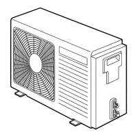
Diagrams illustrating the external structure and dimensions of the 24 Class outdoor unit.
Diagrams illustrating the external structure and dimensions of the 18 Class outdoor unit.
Wiring diagram for specific indoor and outdoor unit models.
Wiring diagram for specific indoor and outdoor unit models.
Wiring diagram for specific indoor and outdoor unit models.
Wiring diagram for specific indoor and outdoor unit models.
List and specifications of electrical components used in the indoor unit.
Electrical parts and specifications for 18 Class outdoor units.
Electrical parts and specifications for 24 Class outdoor units.
Refrigeration cycle diagram for specific indoor/outdoor unit models.
Refrigeration cycle diagram for specific indoor/outdoor unit models.
Refrigeration cycle diagram for specific indoor/outdoor unit models.
Refrigeration cycle diagram for specific indoor/outdoor unit models.
Control block diagram for specific indoor unit models.
Control block diagram for specific indoor unit models.
How the AC operates and its circuit descriptions.
Details on Hi POWER, limit controls, defrost, and auto restart functions.
Procedures for managing filter checks, self-cleaning, and auto restart.
Explains the QUIET and COMFORT SLEEP modes.
Critical safety precautions to be followed during installation.
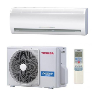
Visual guides and parts lists for unit installation.
Comprehensive guide to installing indoor and outdoor units, including settings.
General troubleshooting steps and initial checks for the unit.
Methods for initial fault judgment and using self-diagnosis via remote control.
Flowcharts for diagnosing specific faulty components.
Troubleshooting common issues with unit components like indoor unit, wiring, P.C. boards, and remote control.
Procedures for replacing key components of the indoor unit.
Procedures for replacing components in specific outdoor unit models.
Procedures for replacing components in specific outdoor unit models.
Exploded view and parts list for the indoor unit's electronic components.
Detailed exploded view and parts list for the indoor unit.
Exploded views and parts lists for various outdoor unit models.
| Power Supply | 220-240V, 50Hz |
|---|---|
| Refrigerant | R410A |
| Energy Efficiency Ratio (EER) | 3.21 |
| Coefficient of Performance (COP) | 3.61 |
| Indoor Unit Weight | 13 kg |