Do you have a question about the Toshiba RAS-24NKP-E and is the answer not in the manual?
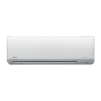
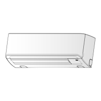
Detailed diagrams of the indoor unit's physical structure and dimensions.
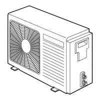
Diagrams illustrating the physical structure and dimensions of the 24 Class outdoor unit.
Diagrams showing the physical structure and dimensions of the 18 Class outdoor unit.
Electrical wiring schematic for specific Toshiba air conditioner models.
Electrical wiring schematic for specific Toshiba air conditioner models.
Electrical wiring schematic for specific Toshiba air conditioner models.
Detailed list of electrical components for the indoor unit model.
Detailed list of electrical components for the outdoor unit model.
Detailed list of electrical components for multiple indoor unit models.
Detailed list of electrical components for specific outdoor unit models.
Detailed list of electrical components for specific outdoor unit models.
Diagram illustrating the refrigerant flow for specific indoor/outdoor units.
Diagram showing refrigerant flow for specific indoor/outdoor units.
Diagram illustrating the refrigerant flow for specific indoor/outdoor units.
Diagram illustrating the refrigerant flow for specific indoor/outdoor units.
Diagram showing the control logic and signal flow for the unit.
Diagram showing control logic and signal flow for various unit models.
Overview of how the indoor and outdoor units control the air conditioner's functions.
Details on how the air louvers operate, including manual and swing modes.
Explanation of the indoor fan motor's speed control and operation modes.
Details on how the unit's circuits operate during different modes and conditions.
Explanation of the unit's operation when only the fan is active.
Details on compressor, valve, and fan control during cooling mode.
Explanation of compressor, valve, and fan control during dry mode.
Details on control for compressor, valve, and fan during heating operation.
Explanation of how the unit automatically selects operation mode based on temperature.
Conditions that trigger the defrost operation based on temperature zones.
Conditions that determine when the defrost operation stops.
Step-by-step guide to enabling the auto restart function.
Procedure to disable the auto restart function.
Procedure to cancel the self-cleaning function.
Procedure to set and enable the self-cleaning function.
Details of comfort sleep mode operation in cooling mode.
Details of comfort sleep mode operation in heating mode.
Essential safety precautions to follow during installation.
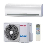
Diagrams showing the placement and mounting of indoor and outdoor units.
Details regarding installation procedures and required parts.
List of optional parts needed for specific installation scenarios.
Catalog of accessories and parts included with the unit for installation.
Specific guidelines and procedures for installing the indoor unit.
Guidelines for selecting the optimal location for indoor unit installation.
Instructions for creating the pipe hole and mounting the installation plate.
Instructions for connecting the unit to the electrical supply.
Detailed steps for connecting the electrical wiring.
Steps for connecting refrigerant piping and installing the drain hose.
Instructions for securely mounting the indoor unit onto the installation plate.
Guidance on proper drain hose setup to ensure effective drainage.
Specific guidelines and procedures for installing the outdoor unit.
Guidelines for selecting the optimal location for outdoor unit installation.
Steps for connecting the refrigerant pipes to the outdoor unit.
Procedure for removing air and moisture from the refrigerant circuit.
Detailed steps for connecting the electrical wiring to the outdoor unit.
Instructions for setting the remote control selector for multi-unit configurations.
Miscellaneous installation procedures and checks.
Procedure for checking the refrigerant system for gas leaks.
How to perform a test run to confirm proper operation after installation.
Instructions for setting the auto restart function.
General steps to follow for troubleshooting issues with the unit.
Initial checks for common problems before detailed diagnosis.
Checking if the power supply voltage is within the normal operating range.
Checking for proper connection of indoor and outdoor unit cables.
Verifying microcomputer control operations against expected behavior.
Initial assessment of faults based on lamp indicators and symptoms.
Using the remote control to access and interpret self-diagnosis check codes.
Steps to enter and operate the remote control in service mode.
Flowcharts for diagnosing specific faulty parts based on symptoms.
Specific troubleshooting guide for indoor unit problems.
Procedure to diagnose why the indoor unit is not turning on.
Procedure to diagnose why the indoor fan motor is not operating.
Procedure to diagnose why the compressor is not operating.
Troubleshooting steps for wiring issues between units.
Diagnosing wiring problems when the outdoor unit fails to operate.
Diagnosing issues where the outdoor unit stops intermittently after startup.
Troubleshooting procedures for P.C. board related issues.
Procedure and checks for diagnosing faults with the indoor P.C. board.
Steps to diagnose and resolve issues with the remote control.
Procedure for replacing the front panel and electrical parts assembly.
Procedures for replacing indoor unit parts like grille, filters, fan, and motor.
Procedure for common part replacement in the outdoor unit.
Procedures for replacing components in specific outdoor unit models.
Exploded diagram and list of parts for the indoor unit's assembly.
Exploded diagram and list of parts for the indoor unit.
Exploded diagram and list of parts for the RAS-18NAH-E outdoor unit.
Exploded diagram and list of parts for the RAS-24NA-E, RAS-24N2AX outdoor units.
Exploded diagram and list of parts for the RAS-18NA-E, RAS-18N2AX outdoor units.
| Power Supply | 220-240V, 50Hz |
|---|---|
| Refrigerant | R410A |
| Energy Efficiency Ratio (EER) | 3.21 |
| Coefficient of Performance (COP) | 3.61 |
| Noise Level (Indoor) | 45 dB(A) |
| Type | Split |