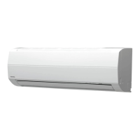
Do you have a question about the Toshiba RAS-24SA-ES and is the answer not in the manual?
| Brand | Toshiba |
|---|---|
| Model | RAS-24SA-ES |
| Category | Air Conditioner |
| Language | English |
Explains functions, display, and button operations of the remote control unit.
Describes the roles of indoor and outdoor unit controllers in managing operations.
Details circuit operations for Cooling, Dry, and Heating modes based on sensor inputs.
Covers low-temperature limit, high-temperature limit, and defrost operations for safety.
Explains the fully automated operation that adjusts settings based on region preferences.
Describes the high-power mode for rapid cooling or heating by adjusting set temperature and fan speed.
Details the quiet mode, reducing indoor fan speed for low noise operation.
Explains energy-saving mode that automatically adjusts temperature settings over time.
Describes a mode for comfortable sleep with automatic temperature adjustments and auto shut-down.
Explains the indicator for filter cleaning status and how to reset it.
Details how the unit restarts with previous settings after a power outage.
Explains the operation to prevent mold and bacteria growth inside the unit by drying.
Provides critical safety warnings and precautions for installation personnel and users.
Visual guide showing placement, clearances, and piping routes for unit installation.
Details optional installation parts, accessories, and outdoor unit fixing bolt arrangement.
Covers optimal placement, drilling, and mounting procedures for the indoor unit.
Covers ideal installation locations and refrigerant piping connection procedures for the outdoor unit.
Covers gas leak testing, system test execution, and remote control settings post-installation.
General steps for diagnosing and resolving operational issues.
Lists fundamental checks like power supply, cable connections, and normal program control.
Guides on initial diagnosis based on symptoms, self-diagnosis lamps, and detective operations.
Procedures for accessing and interpreting error codes via the remote control in service mode.
Flowcharts for diagnosing specific faults like serial signal errors or 4-way valve issues.
Guides for diagnosing specific issues with the indoor unit, such as power or fan motor problems.
Guides for diagnosing wiring issues between indoor and outdoor units.
Guides for diagnosing issues related to the indoor unit's printed circuit board.
Guides for diagnosing issues with the remote control unit's functionality.
Procedures for disassembling and replacing parts of the indoor unit, like the front panel and fan motor.
Procedures for disassembling and replacing electrical components of the outdoor unit.
Exploded view and parts list for the indoor unit's electronic components assembly.
Exploded view and parts list for the indoor unit's main body and components.
Exploded view and parts list for specific outdoor unit models.
Exploded view and parts list for specific outdoor unit models.


