Do you have a question about the Toshiba RAS-B13N3KV2-E and is the answer not in the manual?
Power supply cord requirements for outdoor unit parts.
Precautions for R410A refrigerant and installation.
Critical warnings for installation and operation safety.
Installation warnings, electrical work, piping, grounding, and location.
Further installation cautions regarding water, noise, power supply, drainage, and handling.
Detailed technical specifications for indoor and outdoor units.
Graphs showing compressor speed vs. current and capacity vs. temperature.
Graphs showing capacity changes based on outdoor temperature.
Safety precautions specific to R410A refrigerant installation and servicing.
Guidelines for piping materials, joints, processing, and flare connections.
Steps and procedure for recharging the refrigerant.
Brazing materials, flux, methods, and preventing oxidation.
Lists tools exclusive for R410A and their interchangeability.
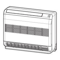
Diagrams showing dimensions and parts of the indoor unit.
Diagrams showing dimensions and parts of the outdoor unit.
List of electrical parts for the indoor unit with types and specs.
List of electrical parts for the outdoor unit with types and specs.
Diagram showing the refrigerant flow for cooling/heating.
Table of operation data for cooling and heating modes.
Block diagram of the indoor unit control system.
Block diagram of the outdoor unit control system.
Overview of the air conditioner's control system and unit roles.
Covers basic, cool/heat, auto, dry operations.
Covers indoor and outdoor fan motor control.
Covers capacity, current release, temperature controls, defrost.
Covers louver, ECO, temporary, self-cleaning, remote A/B selection, quiet, sleep, one-touch, hi-power, filter.
How to set and cancel the auto restart function after power failure.
Covers remote control operation, button functions, and display.
Visual guide for installing indoor and outdoor units, including clearances and piping.
Groups optional parts, accessories, and tools.
Groups installation place, hole cutting, wiring, piping, drain hose.
Groups installation place, piping, evacuating, wiring.
Safety precautions for high voltage circuits and control components.
First confirmation, primary judgment, and LED flash code interpretation.
Self-diagnosis via remote, troubleshooting by symptoms, and wiring failures.
Procedures for checking main parts, P.C. boards, and outdoor fan motor.
Steps to diagnose issues with the outdoor fan motor.
Step-by-step instructions for disassembling and replacing indoor unit parts.
Procedure for removing and replacing the microcomputer.
Procedures for detaching and attaching the outdoor unit's main components.
Exploded view and parts list for the indoor unit.
Exploded view and parts list for the indoor unit (continued).
Exploded view and parts list for the outdoor unit.
Diagram showing the layout of components on the P.C. boards.
| Cooling Capacity | 3.5 kW |
|---|---|
| Heating Capacity | 4.2 kW |
| Energy Efficiency Ratio (EER) | 3.21 |
| Seasonal Energy Efficiency Ratio (SEER) | 6.1 |
| Power Supply | 220-240V, 50Hz |
| Refrigerant | R32 |
| Outdoor Noise Level | 50 dB(A) |
| Coefficient of Performance (COP) | 3.61 |
| Type | Split Type |
| Indoor Noise Level | 19 dB (Low) |
| Noise Level (Indoor) | 19 dB (Low) |