Do you have a question about the Toshiba RAS-B13N3KVP-E and is the answer not in the manual?
Outlines critical safety precautions and procedures for handling R410A refrigerant during installation and servicing.
Details the correct procedures and materials for installing refrigerant piping systems.
Illustrates the flow of refrigerant through the indoor and outdoor units, including key components.
Illustrates the physical layout and placement for installing indoor and outdoor units, including piping.
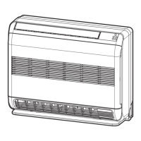
Specifies recommended locations for installing the indoor unit, considering clearance and signal reception.
Provides instructions for cutting wall openings and mounting the indoor unit's installation plate.
Details electrical requirements, power source preparation, and connection methods for safe installation.
Explains the step-by-step process for connecting the indoor unit's power and signal cables.
Covers the procedures for forming refrigerant piping and installing the drain hose for proper function.
Provides detailed steps for physically mounting and securing the indoor unit onto the installation plate.
Explains the correct method for running the drain hose to ensure proper water drainage and prevent leaks.
Specifies optimal locations for installing the outdoor unit, considering noise, wind, and gas exposure.
Explains the flaring process for connecting refrigerant pipes, including dimensions and torque specifications.
Describes the procedure for evacuating air from the refrigerant circuit using a vacuum pump.
Provides instructions for connecting the power supply and communication cables between indoor and outdoor units.
| Cooling Capacity | 3.5 kW |
|---|---|
| Heating Capacity | 4.0 kW |
| Energy Efficiency Ratio (EER) | 3.21 |
| Seasonal Energy Efficiency Ratio (SEER) | 6.1 |
| Power Supply | 220-240V, 50Hz |
| Refrigerant | R32 |
| Indoor Unit Dimensions (W x H x D) | 798 x 293 x 230 mm |
| Outdoor Unit Dimensions (W x H x D) | 660 x 530 x 240 mm |
| Weight (Indoor Unit) | 9 kg |
| Weight (Outdoor Unit) | 30 kg |
| Energy Efficiency Class (Cooling) | A++ |
| Energy Efficiency Class (Heating) | A+ |
| Energy Efficiency Ratio (Cooling) | 3.21 |
| Outdoor Unit Noise Level | 50 dB(A) |
| Type | Split Type |
| Indoor Unit Noise Level (Low) | 21 dB |