EasyManua.ls Logo

Toshiba RAV-182A-PE - User Manual

Toshiba RAV-182A-PE
63 pages
Print Icon
To Next Page IconTo Next Page
Loading...
S
SERVICE MANUAL
FILE NO. A90-9504
AIR-CONDITIONER
RAV-182B-PE/182A-PE
RAV-242B-PE/242A-PE
RAV-242B-PE/242A8-PE
RAV-362B-PE/362A8-PE
RAV-462B-PE/462A8-PE
SPLIT CEILING TYPE
SPLIT BUILT-IN DUCT TYPE
RAV-182U-PE/182A-PE
RAV-242U-PE/242A-PE
RAV-242U-PE/242A8-PE
RAV-362U-PE/362A8-PE
RAV-462U-PE/462A8-PE
SPLIT CASSETTE TYPE
RAV-182K(W)-PE/RAV-182A-PE
RAV-242K(W)-PE/RAV-242A-PE
RAV-242K(W)-PE/RAV-242A8-PE
SPLIT WALL TYPE
RAV-182C-PE/RAV-182A-PE
RAV-242C-PE/RAV-242A-PE
RAV-242C-PE/RAV-242A8-PE
RAV-362C-PE/RAV-362A8-PE
RAV-462C-PE/RAV-462A8-PE
PRINTED IN U.K. Nov. 1995
Heronhill - for all your Toshiba requirements
Tel: 01823 665660
www.heronhill.co.uk
Fax: 01823 665807
Question and Answer IconNeed help?

Do you have a question about the Toshiba RAV-182A-PE and is the answer not in the manual?

Summary

1. SPECIFICATIONS

2. CONSTRUCTION VIEWS

Indoor Unit Construction Views

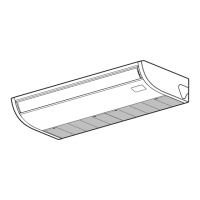
Diagrams and dimensions for various indoor unit models.

Outdoor Unit Construction Views

Diagrams and dimensions for various outdoor unit models.

3. WIRING DIAGRAMS

Indoor Unit Wiring Diagrams

Wiring diagrams for various indoor unit types (Duct, Ceiling, Wall, Cassette).

Outdoor Unit Wiring Diagrams

Wiring diagrams for various outdoor unit models.

4. SPECIFICATIONS OF ELECTRICAL PARTS

Indoor Unit Electrical Parts

Electrical component specifications for various indoor unit models.

Outdoor Unit Electrical Parts

Electrical component specifications for various outdoor unit models.

5. REFRIGERANT PIPING DIAGRAM

5.1 Indoor Unit Piping

Refrigerant piping diagram for indoor units.

5.2 Indoor Unit Piping

Refrigerant piping diagram for indoor units.

6. REMOTE CONTROLLER

6.1 Remote Controller Overview

Description and operation of the remote control unit.

6.2 Controller Function Details

Detailed explanation of remote controller button functions and operations.

6.3 Timer Operation

Explanation of timer settings and operations.

6.4 Malfunction Check Monitor

Monitoring and diagnosing operational malfunctions.

6.4.1 Reading Malfunction Display

Guide on interpreting malfunction check codes and displays.

6.4.2 List of Check Codes

Table of diagnostic functions, symptoms, and actions for check codes.

7. OUTLINE OF CONTROL CIRCUIT

7.1 Operation Mode Control

How operation modes are selected and controlled.

7.2 Temperature & Fan Speed Control

Details on room temperature and fan speed control settings.

7.3 Test Operation

Procedure for performing a test operation of the unit.

8. CONTROL CIRCUIT DESCRIPTIONS

8.1 Indoor Unit Control Circuit Diagram

Schematic diagram of the indoor unit's control circuit.

Outdoor Unit Control Circuit Diagram

Schematic diagram of the outdoor unit's control circuit.

Sensor, Power, and Reset Circuits

Details on sensor, power source, reset, and timer circuits.

Signal, Relay, and Switch Circuits

Explanation of serial signals, optional circuits, float switch, relays, and switches.

9. WIRING FOR GROUP OPERATION

10. PERFORMANCE CHARACTERISTICS

10.1 Cooling Capacity Charts

Performance charts for cooling capacity based on temperature and piping length.

10.2 Piping Length vs. Cooling Capacity

Charts showing cooling capacity adjustments based on piping length and height.

10.3 Refrigerant Volume and Piping

Table detailing refrigerant amounts for piping lengths and recharge times.

10.4 Air Flow Distribution

Information on airflow direction and volume ratios for different units.

11. EXPLODED VIEWS AND PARTS LISTS

Indoor Unit Assemblies

Exploded views and parts lists for various indoor unit types.

Outdoor Unit Assemblies

Exploded views and parts lists for various outdoor unit models.

Toshiba RAV-182A-PE Specifications

General IconGeneral
BrandToshiba
ModelRAV-182A-PE
CategoryAir Conditioner
LanguageEnglish

Related product manuals