Do you have a question about the Toshiba RAV-SM2804AT8-A and is the answer not in the manual?
| Type | Split System |
|---|---|
| Refrigerant | R410A |
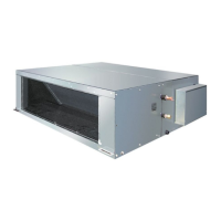
| Indoor Unit Dimensions (W x H x D) | 1, 940 x 690 x 700 mm |
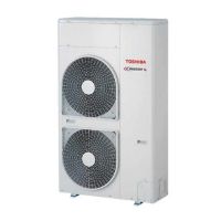
| Outdoor Unit Dimensions (W x H x D) | 1, 190 x 1, 600 x 380 mm |
| Power Supply | 3 Phase, 380-415V, 50Hz |
| Power Source | 3 Phase, 380-415V, 50Hz |
Manual for the outdoor unit of the split type air conditioner.
Details on cooling/heating capacity, electrical characteristics, appearance, and fan for indoor units.
Details on power supply, compressor, refrigerant, dimensions, and fan for outdoor units.
Curves showing current vs. compressor speed and capacity ratio vs. temperature.
Diagrams illustrating external dimensions and connection points of the outdoor unit.
Electrical wiring schematic for the outdoor unit, showing connections between components.
List of electrical components for the outdoor unit with their specifications.
Safety precautions for handling R410A refrigerant during installation and servicing.
Guidelines for selecting and installing piping materials and joints for R410A.
Required tools and their interchangeability for R410A systems.
Step-by-step procedure for recharging refrigerant.
Details on brazing materials, flux, and methods for pipe connections.
Guidelines for reusing existing R22 or R407C piping for R410A models.
Details on the control system for the outdoor unit and its main controls.
Overview of common problems and troubleshooting procedures for wired remote controllers.
Procedure to view past error histories recorded by the indoor unit.
Explanation of how to control multiple indoor units with a single remote controller.
Steps for setting up indoor unit addresses and group addresses.
Terminology and system configurations for address setup and group control.
Wiring instructions for remote controllers for single, twin, triple, and double twin systems.
Step-by-step guide for manually setting addresses via the remote controller.
Methods to check indoor unit addresses and positions on the remote controller.
Outline of the steps involved in exchanging the compressor.
Procedures for disassembling and assembling parts of the outdoor unit.
Illustrated parts list and exploded views for the outdoor unit.
Parts list and diagrams for the inverter assembly.