Do you have a question about the Toshiba RAV-SM2804AT8-E and is the answer not in the manual?
Explains the meaning of various warning indications used in the manual.
Explains the meaning of illustrated symbols and marks used in the manual.
Guidance on checking warning labels on the main unit for safety.
Safety precautions related to the use of R410A refrigerant.
Specific warnings and best practices for installing and servicing R410A systems.
Information on suitable pipe materials and their specifications for R410A.
Lists essential tools specifically required for R410A refrigerant systems.
Indoor/outdoor unit combination patterns for the RAV-SM2244AT series.
Indoor/outdoor unit combination patterns for the RAV-SM2804AT series.
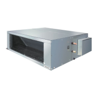
Technical specifications for various indoor unit types.
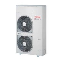
Technical specifications for the outdoor unit models.
Performance curves showing operational characteristics under different conditions.
External views and dimensions of the outdoor unit.
Wiring diagram for the outdoor unit and its components.
Detailed specifications for electrical parts used in the outdoor unit.
Details on outdoor unit control systems and circuit configurations.
Overview of the main control functions and operations of the system.
General overview and common troubleshooting steps for system issues.
Detailed troubleshooting procedures and error code explanations.
Procedure to view past error codes and system logs.
How to configure and operate multiple indoor units in a group.
Various settings and configurations for the outdoor unit.
Step-by-step guide for setting unit addresses for system operation.
Details on setting up addresses and managing group control configurations.
Wiring diagrams and guidelines for connecting remote controllers.
Manual procedure for setting unit addresses via the remote controller.
How to check the position and address of indoor units in the system.
General outline for the compressor replacement procedure.
Detailed steps for the compressor exchange process.
Procedures for detaching and attaching parts of the outdoor unit.
Exploded view and parts list for the outdoor unit.
Exploded view and parts list for the inverter assembly.
Exploded view and parts list for the outdoor unit (different models).
Exploded view and parts list for the inverter assembly (different models).
Procedures for ensuring refrigerant concentration limits are met in installed rooms.
| Indoor Unit Dimensions (WxHxD) | 1600x690x248 mm |
|---|---|
| Outdoor Unit Dimensions (WxHxD) | 990x1240x380 mm |
| Weight (Indoor Unit) | 44 kg |
| Weight (Outdoor Unit) | 118 kg |
| Cooling Capacity | 2.8 kW |
| Energy Efficiency Ratio (EER) | 3.50 |
| Seasonal Energy Efficiency Ratio (SEER) | 5.60 |
| Power Source | 380-415/3/50 V/Phase/Hz |
| Energy Efficiency Ratio (Cooling) | 3.50 |