Do you have a question about the Toshiba RAV-SP804ATP-A and is the answer not in the manual?
Defines requirements for qualified personnel for installation, maintenance, and repair.
Details protective gear required for various work tasks.
Explains the meaning of safety indications (DANGER, WARNING, CAUTION) and illustrated marks.
Lists warnings for electrical shock, moving parts, high temperatures, and fin hazards.
Emphasizes circuit breaker use and capacitor discharge for electrical safety.
Covers general safety practices, use of protective clothing, and qualified personnel.
Details safety for wiring, grounding, and using specified parts.
Provides precautions for refrigerant handling, brazing, and fire safety.
Discusses R410A pressure, potential hazards, and proper handling.
States compliance with directives and harmonized standards.
Provides instructions for disposing of the unit according to WEEE regulations.
Lists key specifications for outdoor units, including sound levels and weight.
Highlights R410A pressure, tool requirements, and installation precautions.
Specifies suitable copper pipe and joint materials for R410A systems.
Lists tools exclusive to R410A and their interchangeability.
Lists common tools required for both R22 and R410A systems.
Provides detailed technical specifications for the outdoor units.
Illustrates current draw based on compressor speed under different conditions.
Shows how the unit's capacity changes with outdoor temperature.
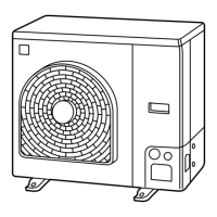
Presents external views and dimensions for the RAV-SP56*ATP* model.
Details external views and dimensions for the RAV-SP80*ATP* model.
Shows the refrigerating cycle for single and twin indoor unit configurations.
Illustrates the refrigerating cycle and operating parameters for RAV-SP56*ATP*.
Shows the refrigerating cycle and operating parameters for RAV-SP80*ATP*.
Presents the electrical wiring diagram for the RAV-SP56*ATP* outdoor unit.
Displays the electrical wiring diagram for the RAV-SP80*ATP* outdoor unit.
Lists specifications for electrical components in the RAV-SP56*ATP*.
Lists specifications for electrical components in the RAV-SP80*ATP*.
Emphasizes safety precautions for R410A installation and servicing due to higher pressure.
Details copper pipe and joint specifications suitable for R410A.
Covers pipe cutting, burr removal, and cleanliness requirements.
Explains flare processing methods and dimensions for R410A/R22.
Provides tables for flare nut and pipe dimensions for R410A and R22.
Details flare connection, torque values, and oil application precautions.
Lists the tools necessary for refrigerant handling.
Outlines the procedure for recovering and charging refrigerant.
Describes different brazing filler materials and their applications.
Explains the necessity and types of flux for brazing.
Details brazing techniques, nitrogen flow for oxidation prevention, and flux removal.
Lists conditions for reusing existing pipes (dryness, cleanliness, tightness).
Identifies cases where existing pipes cannot be reused and require cleaning or replacement.
Addresses reuse of branching pipes for simultaneous operation systems.
Explains how to cure pipes to prevent rust and moisture entry when units are opened.
Details checks for trial run, existing pipe condition, and switch settings.
Lists checks for existing pipes and cautions for reuse, including model-specific settings.
Outlines limitations on additional refrigerant charging and measures for leakage.
Describes controls like PMV operation, discharge temperature release, and sensor functions.
Explains cooling fan speed control based on sensors and operation frequency.
Details heating fan speed control related to temperature sensors and compressor status.
Describes heating the compressor to prevent refrigerant stagnation.
Explains compressor protection during short intermittent operation.
Controls compressor speed based on current to prevent inverter overload.
Details control values based on TO sensor for electronic part protection.
Explains compressor stopping due to abnormal current.
Restrains high pressure rise using TL/TC sensors, stopping the compressor.
Explains defrost initiation and termination conditions for SP56.
Details defrost logic and jumper settings for SP80.
Explains compressor protection against oil accumulation.
Identifies components and connectors on the RAV-SP56*ATP* P.C. board.
Lists components and connectors on the RAV-SP80*ATP* P.C. board.
Provides general guidelines, required tools, and confirmation points for troubleshooting.
Outlines the process for diagnosing issues using error codes and lamp indications.
Explains how to interpret indoor unit error codes via lamp indications.
Lists various indoor unit errors including sensor, EEPROM, and compressor issues.
Describes error codes not covered by specific check codes, like test run issues.
Details outdoor unit error codes, detection methods, and their explanations.
Continues listing outdoor unit error codes and their detection methods.
Provides step-by-step troubleshooting for indoor unit errors.
Lists error modes related to remote and central controller communication.
Details error modes detected by the outdoor unit, including sensor and overheat issues.
Covers troubleshooting for discharge temperature, power supply, and fan system errors.
Guides diagnosing communication errors using LED displays for SP56.
Provides troubleshooting for sensor errors, compressor breakdown, and lock for SP56.
Covers troubleshooting for current detection, power supply, and temperature errors for SP56.
Guides diagnosing valve, fan system, short-circuit, and position detection errors for SP56.
Details diagnosing communication errors using LED displays for SP80.
Covers troubleshooting for discharge, heat exchanger, and TL sensor errors for SP80.
Guides diagnosing TO, TS, TH sensor, miswiring, and EEPROM errors for SP80.
Details troubleshooting for compressor breakdown, lock, and current detection errors for SP80.
Covers troubleshooting for case thermostat and unset model type errors for SP80.
Guides diagnosing communication, sensor, overheat, gas leak, and valve errors for SP80.
Details troubleshooting for discharge temp, power supply, and voltage errors for SP80.
Guides diagnosing heat sink overheat and gas leak detection errors for SP80.
Details troubleshooting for the 4-way valve reversal error for SP80.
Guides diagnosing high pressure protective operation errors for SP80.
Details troubleshooting for fan system, short-circuit, and position detection errors for SP80.
Provides resistance values for temperature sensors at various temperatures.
Shows resistance values for compressor windings and fan motor windings.
Explains the operation of the refrigerant recovery switch (pump down).
Details DIP switch and jumper settings for various operational modes.
Explains the use of DIP switches and LEDs for setup and error display.
Describes how to use switches to select LED display modes for errors and sensor data.
Details confirming errors using LED displays and wired remote controller codes.
Explains how to view detected sensor values, current, compressor frequency, and PMV opening.
Describes maintenance operations like test runs and forced fan/PMV operation.
Details operations for 4-way valve, self-hold valve, SV valve, and output relays.
Provides instructions for detaching and attaching parts of the RAV-SP56*ATP* outdoor unit.
Details the procedure for removing and installing the front cabinet.
Guides inverter assembly detachment, including capacitor discharging safety.
Details removing inverter assembly connectors, highlighting lock mechanisms.
Guides replacing the control P.C. board, including heat sink and safety notes.
Details detachment and attachment of the rear cabinet.
Provides instructions for fan motor replacement, including torque specs.
Details compressor removal and replacement, including safety precautions.
Provides instructions for reactor removal and attachment.
Details detachment and attachment of the PMV coil.
Provides instructions for fan guard removal and attachment.
General procedures for detaching/attaching parts of the RAV-SP80*ATP* unit.
Details removal of the discharge port cabinet and related parts.
Provides instructions for removing the side cabinet.
Guides replacing the control P.C. board, including connector removal and safety.
Details reactor replacement, including connector and bundling band handling.
Provides instructions for fan motor replacement, including torque specs and lead routing.
Details compressor removal, including piping, sensors, and lead wires.
Continues compressor removal steps, including burner use and safety warnings.
Guides compressor mounting, including lead wire wrapping and sensor routing.
Explains the vacuuming process and PMV operation notes.
Details adding the specified quantity of refrigerant.
Provides instructions for PMV coil detachment and attachment.
Details fan guard removal and attachment procedures.
Shows an exploded view of the RAV-SP564ATP-A outdoor unit.
Lists parts with location and part numbers for RAV-SP564ATP-A.
Illustrates the components within the inverter assembly.
Lists part numbers for inverter assembly components.
Presents an exploded view of the RAV-SP804ATP-A outdoor unit.
Lists parts with location and part numbers for RAV-SP804ATP-A.
Shows further components within the inverter assembly.
Lists part numbers for inverter assembly components.
Discusses refrigerant concentration limits and necessary ventilation measures.
| Brand | Toshiba |
|---|---|
| Model | RAV-SP804ATP-A |
| Category | Air Conditioner |
| Language | English |