EasyManua.ls Logo

Toshiba RAV-SP800AT-E User Manual

Toshiba RAV-SP800AT-E
248 pages
To Next Page IconTo Next Page
Page #1 background imageLoading...
Page #1 background image
R410A
FILE NO. A03-003F
PRINTED IN JAPAN, Jun.,2004 ToMo
SERVICE MANUAL/INTEGRATION
SPLIT TYPE
OUTDOOR UNIT
<SUPER DIGITAL INVERTER>
RAV-SP560AT-E, RAV-SP800AT-E, RAV-SP1100AT-E, RAV-SP1400AT-E
<DIGITAL INVERTER>
RAV-SM560AT-E, RAV-SM800AT-E, RAV-SM1100AT-E, RAV-SM1400AT-E
INDOOR UNIT
<SUPER DIGITAL INVERTER>
RAV-SP1100UT-E
<DIGITAL INVERTER>
RAV-SM560UT-E, RAV-SM560BT-E, RAV-SM561BT-E, RAV-SM561CT-E,
RAV-SM800UT-E, RAV-SM800BT-E, RAV-SM801BT-E, RAV-SM801CT-E,
RAV-SM1100UT-E, RAV-SM1101CT-E, RAV-SM1101BT-E,
RAV-SM1400UT-E, RAV-SM1401CT-E, RAV-SM1401BT-E
Toshiban lämmitys- ja jäähdytyslaitteiden jälleenmyyjä pääkaupunkiseudulla on Jäähdytinpalvelu RefGroup Oy
www.ilmalämpöpumput.com

Table of Contents

Question and Answer IconNeed help?

Do you have a question about the Toshiba RAV-SP800AT-E and is the answer not in the manual?

Toshiba RAV-SP800AT-E Specifications

General IconGeneral
BrandToshiba
ModelRAV-SP800AT-E
CategoryAir Conditioner
LanguageEnglish

Summary

ADOPTION OF NEW REFRIGERANT

WARNING

Service Manual Table

NOTICE

1. SPECIFICATIONS

1-1. Indoor Unit

Specifies technical details of various indoor unit types.

1-2. Outdoor Unit

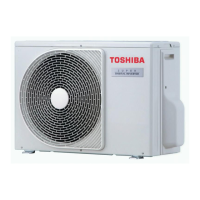
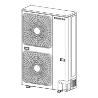
Specifies technical details of various outdoor unit types.

1-3. Combination Specifications of Indoor Units with Outdoor Units

Details how indoor and outdoor units can be combined.

1-4. Operation Characteristic Curve

Illustrates performance characteristics based on operating conditions.

2. AIR DUCTING WORK

2-1. Static Pressure Characteristics of Each Model

Shows static pressure characteristics for different models.

3. CONSTRUCTION VIEWS (EXTERNAL VIEWS)

3-1. Indoor Unit

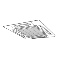
Provides construction views for various indoor unit types.

3-2. Outdoor Unit

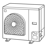
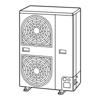
Provides construction views for various outdoor unit types.

4. SYSTEMATIC REFRIGERATING CYCLE DIAGRAM

4-1. Indoor Unit/Outdoor Unit

Details the refrigerating cycle for indoor and outdoor units.

5. WIRING DIAGRAM

5-1. Indoor Unit

Shows wiring diagrams for various indoor unit types.

5-2. Outdoor Unit

Shows wiring diagrams for various outdoor unit types.

6. SPECIFICATIONS OF ELECTRICAL PARTS

6-1. Indoor Unit

Specifies electrical parts for indoor units.

6-2. Outdoor Unit

Specifies electrical parts for outdoor units.

6-3. Accessory Separate Soldparts

Lists optional accessory parts that are sold separately.

7. REFRIGERANT R410A

7-1. Safety During Installation/Servicing

Details safety precautions for handling R410A during installation and servicing.

7-2. Refrigerant Piping Installation

Covers guidelines for installing refrigerant piping with R410A.

7-3. Tools

Lists required tools for installation and servicing R410A systems.

7-4. Recharging of Refrigerant

Explains the procedure for recharging refrigerant.

7-5. Brazing of Pipes

Details the process and materials for brazing pipes.

8. CONTROL BLOCK DIAGRAM

8-1. Indoor Control Circuit

Shows the control circuit diagram for indoor units.

9. CIRCUIT CONFIGURATION AND CONTROL SPECIFICATIONS

9-1. Microcomputer System Block Diagram

Provides a system block diagram of the microcomputer controls.

9-2. Indoor Control Circuit

Details the control circuits within the indoor units.

9-3. Outdoor Controls

Outlines the control mechanisms for the outdoor units.

10. TROUBLESHOOTING

10-1. Summary of Troubleshooting

Offers a summary of the troubleshooting process and initial checks.

10-2. Check Code List

Lists error codes detected by the indoor unit.

10-3. Error Mode Detected by LED on Outdoor P.C. Board

Explains error modes detected via LEDs on the outdoor P.C. board.

10-4. Troubleshooting Procedure for Each Check Code

Provides step-by-step procedures for specific check codes.

11. REPLACEMENT OF SERVICE INDOOR P.C. BOARD

12. SETUP AT LOCAL SITE AND OTHERS

12-1. Indoor Unit

Details setup procedures specifically for indoor units.

12-2. Network Adapter

Details the network adapter and its specifications.

12-3. How to Set an Address Number

Provides instructions for setting network address numbers.

12-4. Display and Operation of Main Remote Controller and Central Control Remote Controller

Compares display and operation of main and central remote controllers.

13. ADDRESS SETUP

13-1. Address Setup

Details the procedure for setting unit addresses.

13-2. Address Setup & Group Control

Explains address setup and group control configurations.

13-3. Address Setup

Provides further details on address setup procedures.

14. DETACHMENTS

14-1. Indoor Unit

Details detachment and attachment procedures for indoor unit components.

14-2. Outdoor Unit

Details detachment and attachment procedures for outdoor unit components.

15. EXPLODED VIEWS AND PARTS LIST

15-1. Indoor Unit

Provides exploded views and parts lists for indoor units.

15-2. Outdoor Unit

Provides exploded views and parts lists for outdoor units.

15-3. Replacement of Main Parts (Sold Separately)

Details the replacement of main parts sold separately.

Related product manuals