Do you have a question about the Toshiba RAV-SP1400AT-E and is the answer not in the manual?
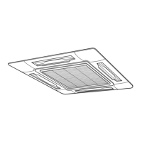
Details for 4-Way Air Discharge Cassette Type Indoor Unit.
Specifications for RAV-SM560AT-E and RAV-SM800AT-E outdoor units.
Compatibility table for indoor and outdoor unit combinations.
Graphs showing performance curves for cooling and heating operations.
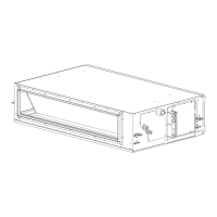
Static pressure characteristics for concealed duct type models.
External views and dimensions of various indoor unit types.
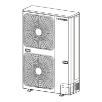
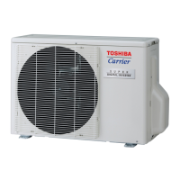
External views and dimensions of outdoor units.
Diagram of the refrigerating cycle connecting indoor and outdoor units.
Wiring diagrams for 4-way air discharge cassette and concealed duct indoor units.
Wiring diagrams for outdoor units.
Specifications for electrical parts of indoor units (fan motor, sensors).
Specifications for electrical parts of outdoor units (fan motor, compressor, sensors).
Details on separately sold accessory parts like drain kits and panels.
Essential safety precautions for R410A installation and servicing.
Guidelines for installing refrigerant piping using R410A.
List of required tools for refrigerant handling and installation.
Procedure for safely recharging refrigerant into the system.
Materials and techniques for brazing pipes with R410A.
Block diagram of the indoor unit's control circuit.
Specifications and operational logic for unit controls.
Diagram showing the layout of components on the indoor unit's main P.C. board.
Block diagram of the microcomputer system for unit control.
Detailed circuit diagrams for indoor unit controls.
Overview of control functions for the outdoor unit.
Overview of troubleshooting steps and common issues.
List of error codes and their corresponding causes and judgments.
Interpreting LED indicators on the outdoor P.C. board for error detection.
Step-by-step procedures for diagnosing and resolving specific check codes.
Procedure for troubleshooting using the central remote controller's CHECK display.
Table of error modes detected by indoor unit, causes, and judgments.
List of error modes detected in the outdoor unit and their causes/measures.
Steps for replacing the service indoor P.C. board assembly.
Procedure to read setup data from EEPROM before replacing the P.C. board.
Procedure for replacing the service P.C. board.
Procedure for writing setup data into EEPROM after replacing the P.C. board.
Setup procedures for indoor units at the installation site.
Procedure for performing a test run setup using the remote controller.
Procedure for selecting functions using the remote controller.
Instructions for cabling and setting up remote controllers.
Using the remote controller to monitor sensor temperature display.
How to view past error history recorded by the remote controller.
Information on the optional network adapter for AI net connection.
Specifications for communication cables used with network adapters.
Instructions for connecting network adapter cables in group control.
Procedure for setting network addresses for indoor units via remote controller or switch.
Comparison of display and operation between main and central remote controllers.
Procedure for manually setting indoor and outdoor unit addresses.
Setting addresses and configuring group control for multiple units.
Manual address setup steps using the remote controller.
Procedure to confirm the indoor unit number and address.
Confirming unit numbers in group control via address.
Procedures for detaching and attaching parts of the indoor unit.
Procedure for replacing the distributor assembly.
Disassembly and reassembly steps for built-in type indoor units.
Supplementary instructions for removing the electric parts box.
Disassembly and reassembly steps for concealed duct type indoor units.
Disassembly and reassembly steps for under ceiling type indoor units.
Procedures for detaching and attaching parts of the outdoor unit.
Exploded views and parts lists for indoor unit components.
Exploded views and parts lists for built-in type indoor units.
Exploded views and parts lists for concealed duct type indoor units.
Exploded views and parts lists for under ceiling type indoor units.
Exploded views and parts lists for outdoor unit components.
Procedures for replacing main parts sold separately.
Procedure for replacing the wireless remote control kit.
List of recommended parts for installing cord heaters.
Tools required for the cord heater installation.
Wiring diagram for cord heater installation.
Step-by-step procedure for installing cord heaters.
Table showing compatible combinations of indoor and outdoor units.
List of service parts for 4-way cassette type units.
Specifications for concealed duct type units.
List of service parts for concealed duct type units.
List of service parts for under ceiling type units.
Procedure for replacing service P.C. boards.
| Model | RAV-SP1400AT-E |
|---|---|
| Cooling Capacity | 12.5 kW |
| Heating Capacity | 14.0 kW |
| Power Supply | 3 Phase, 400V, 50Hz |
| Refrigerant | R410A |
| Type | Air Conditioner |