EasyManua.ls Logo

Toshiba RAV-SP1100UT-E User Manual

Toshiba RAV-SP1100UT-E
118 pages
To Next Page IconTo Next Page
Page #1 background imageLoading...
Page #1 background image
FILE NO. A03-014
SERVICE MANUAL
SPLIT TYPE
RAV-SP1100UT-E
RAV-SP560AT-E, RAV-SP800AT-E
RAV-SP1100AT-E, RAV-SP1400AT-E
PRINTED IN JAPAN, Feb.,2004 ToMo
4-way Air Discharge Cassette type
Concealed Duct type
Under Ceiling type
High wall type
Indoor unit
RAV-SM560UT-E
RAV-SM800UT-E
RAV-SM1400UT-E
RAV-SM561BT-E
RAV-SM801BT-E
RAV-SM1101BT-E
RAV-SM1401BT-E
RAV-SM561CT-E
RAV-SM801CT-E
RAV-SM1101CT-E
RAV-SM1401CT-E
RAV-SM560KRT-E
RAV-SM800KRT-E
Service Manual No.
A02-013
A02-013
A03-003
A03-007
A03-007
A03-007
A03-007
A03-015
A03-015
A03-015
A03-015
A02-013
A02-013
R410A
The type of all the indoor units described in this Service Manual is a new model, RAV-SP1100UT-E only.
For the other indoor units to be combined, refer to the Service Manuals for the following models.
Question and Answer IconNeed help?

Do you have a question about the Toshiba RAV-SP1100UT-E and is the answer not in the manual?

Toshiba RAV-SP1100UT-E Specifications

General IconGeneral
ModelRAV-SP1100UT-E
Cooling Capacity10.0 kW
Heating Capacity11.2 kW
Power Supply220-240V, 50Hz
RefrigerantR410A
Noise Level (Outdoor Unit)52 dB(A)
Outdoor Unit Dimensions (HxWxD)890x900x320 mm

Summary

1. System Specifications

1-1. Indoor Unit Specifications

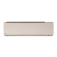
Details specifications for the indoor unit, including dimensions and components.

1-2. Outdoor Unit Specifications

1-4. Operation Characteristic Curve

1-4. Capacity Variation Ratio by Temperature

3. SYSTEMATIC REFRIGERATING CYCLE DIAGRAM

3-1. Indoor/Outdoor Unit Cycle

Shows the detailed refrigerating cycle diagram for specific unit combinations.

4. WIRING DIAGRAM

4-1. Indoor Unit Wiring Diagram

Wiring diagram specific to the RAV-SP1100UT-E indoor unit.

4-2. Outdoor Unit Wiring Diagram

5. SPECIFICATIONS OF ELECTRICAL PARTS

6. REFRIGERANT R410A

6-1. Safety During Installation/Servicing

Essential safety precautions for installation and servicing with R410A refrigerant.

6-3. Tools

6-4. Recharging of Refrigerant

6-5. Brazing of Pipes

7. INDOOR CONTROL

7-2. Control Specifications

7-3. Indoor Print Circuit Board

8. OUTDOOR CONTROL

4. Outdoor Fan Control

8-2. Outdoor Controls

9. TROUBLESHOOTING

9-1. Summary of Troubleshooting

Provides an overview of troubleshooting steps, required tools, and normal operation checks.

9-2. Check Code List

9-3. Outdoor P.C. Board Error Detection

9-4. Troubleshooting Procedures

9-4-1. Central Control Troubleshooting

Step-by-step troubleshooting for central control check codes.
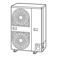
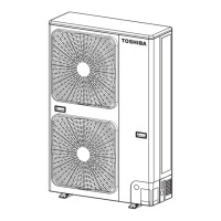
10. SERVICE INDOOR P.C. BOARD REPLACEMENT

11. SETUP AT LOCAL SITE AND OTHERS

11-1-3. Remote Controller Cabling & Setting

11-2. Network Adapter

11-3. Setting Network Address Number

11-4. Remote Controller Display & Operation Comparison

12. ADDRESS SETUP

12-2. Address Setup & Group Control

12-3. Manual Address Setup via Remote Controller

4. Cord Heater Installation Work Procedure

Related product manuals