EasyManua.ls Logo

Toshiba RAV-SP1100AT-E - User Manual

Toshiba RAV-SP1100AT-E
248 pages
Print Icon
To Next Page IconTo Next Page
Loading...
R410A
FILE NO. A03-003F
PRINTED IN JAPAN, Jun.,2004 ToMo
SERVICE MANUAL/INTEGRATION
SPLIT TYPE
OUTDOOR UNIT
<SUPER DIGITAL INVERTER>
RAV-SP560AT-E, RAV-SP800AT-E, RAV-SP1100AT-E, RAV-SP1400AT-E
<DIGITAL INVERTER>
RAV-SM560AT-E, RAV-SM800AT-E, RAV-SM1100AT-E, RAV-SM1400AT-E
INDOOR UNIT
<SUPER DIGITAL INVERTER>
RAV-SP1100UT-E
<DIGITAL INVERTER>
RAV-SM560UT-E, RAV-SM560BT-E, RAV-SM561BT-E, RAV-SM561CT-E,
RAV-SM800UT-E, RAV-SM800BT-E, RAV-SM801BT-E, RAV-SM801CT-E,
RAV-SM1100UT-E, RAV-SM1101CT-E, RAV-SM1101BT-E,
RAV-SM1400UT-E, RAV-SM1401CT-E, RAV-SM1401BT-E
Toshiban lämmitys- ja jäähdytyslaitteiden jälleenmyyjä pääkaupunkiseudulla on Jäähdytinpalvelu RefGroup Oy
www.ilmalämpöpumput.com

Table of Contents

Question and Answer IconNeed help?

Do you have a question about the Toshiba RAV-SP1100AT-E and is the answer not in the manual?

Summary

1. SPECIFICATIONS

1-1. Indoor Unit

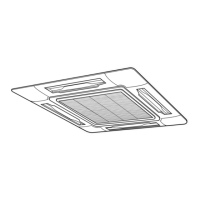
Detailed specifications for various indoor unit types, including 4-Way Air Discharge Cassette.

2. AIR DUCTING WORK

2-1. Static Pressure Characteristics of Each Model

Provides static pressure characteristics for different models related to air ducting.

3. CONSTRUCTION VIEWS (EXTERNAL VIEWS)

3-1. Indoor Unit

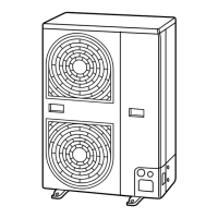
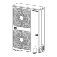
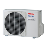
External views and dimensions of the indoor unit, covering various types.

4. SYSTEMATIC REFRIGERATING CYCLE DIAGRAM

4-1. Indoor Unit;Outdoor Unit

Diagram illustrating the refrigerating cycle connecting indoor and outdoor units.

5. WIRING DIAGRAM

5-1. Indoor Unit

Detailed wiring diagram for the indoor unit, including component connections.

6. SPECIFICATIONS OF ELECTRICAL PARTS

6-1. Indoor Unit

Lists electrical parts specifications for indoor units like fan motors and sensors.

7. REFRIGERANT R410 A

7-1. Safety During Installation;Servicing

Crucial safety precautions for handling R410A refrigerant during installation and servicing.

8. CONTROL BLOCK DIAGRAM

8-1. Indoor Control Circuit

Block diagram illustrating the control circuit for the indoor unit.

9. CIRCUIT CONFIGURATION AND CONTROL SPECIFICATIONS

9-1. Microcomputer System Block Diagram

Block diagram of the microcomputer system for circuit configuration and control.

10. TROUBLESHOOTING

10-1. Summary of Troubleshooting

General overview and initial steps for troubleshooting the air conditioning system.

11. REPLACEMENT OF SERVICE INDOOR P.C. BOARD

12. SETUP AT LOCAL SITE AND OTHERS

12-1. Indoor Unit

Procedures for setting up the indoor unit, including test run and function selection.

13. ADDRESS SETUP

13-1. Address Setup

Instructions for setting indoor and outdoor unit addresses for group control.

14. DETACHMENTS

14-1. Indoor Unit

Procedures for detaching and attaching parts of the indoor unit.

15. EXPLODED VIEWS AND PARTS LIST

15-1. Indoor Unit

Exploded views and parts list for various indoor unit types.

16. CORD HEATER INSTALLATION WORK

16-1. Required parts for installation work (Recommendation)

List of recommended parts and specifications for cord heater installation.

APPENDIX-1

1. SDI combination, Indoor; Outdoor

Details on SDI combinations for indoor and outdoor units.

Toshiba RAV-SP1100AT-E Specifications

General IconGeneral
BrandToshiba
ModelRAV-SP1100AT-E
CategoryAir Conditioner
LanguageEnglish

Related product manuals