Instructions for G9000 Series UPS RemotEye – 90000-004 Page 6 of 8
3.0 INSTALL REMOTEYE 4
This step provides instructions for mounting and connecting the RemotEye 4 in the G9000
Series UPS.
NOTE: Numbered components in Figures 11-13 correspond to the numbered entries of the Kit
Contents Table on Page 1.
3.1 Orient the PCB Mounting Box, Figure 11-(3) so the back connector is on the same side
as the RemotEye 4 Mounting Bracket angle and press the mounting box into the
mounting bracket until the retaining tabs, Figure 11-(3T), engage. Secure it with two of
the panhead Philips 6/32 x 3/8” screws, Figure 11-(4.3a).
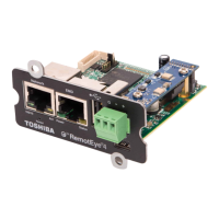
3.2 Connect the Edge Card Connector, Figure 11-(2a), of the RemotEye
4 Comm Cable, Figure 11-(2b) to the RemotEye 4 PCB.
3.3 Remove the Adapter Plug, Figure 10, from the G9000 PSAU-60
Communications board connector CN-1.
3.4 Insert the RemotEye 4 PCB into the PCB Mounting Box and secure
it with two of the panhead Philips 6/32 x 3/8” screws, Figure 11-
(4.3b).
Figure 11: Install RemotEye 4 on Mounting Plate
3.5 Connect the ribbon cable’s RMTI CONN plug, Figure 12/13-(2b), to the RMTI CONN
plug of the RemotEye 4 to COMM BOARD wire assembly, Figure 12/13-(2c).
3.6 Connect the female D-SUB9, Figure 12/13-(2f), and CN2, Figure 12/13-(2g), plugs of
the RemotEye 4 Comm Cable, Figure 12/13-(2e), to the G9000 PSAU-60 Comm Board.
 Loading...