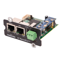
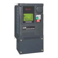
The TOSVERT VF-PS1 series BACnet® Option unit, BCN001Z, is designed to enable the VF-PS1 series inverter to be connected to a BACnet® network, specifically operating as an Application Specific Controller (B-ASC). This manual, E6581440, provides comprehensive instructions for its installation, operation, and maintenance, ensuring the correct and complete utilization of its capabilities. It is crucial for end-users to read this manual before installing or operating the unit and to keep it in a safe place for future reference. The BCN001Z is compatible with VF-PS1 software version V620 or later.
Function Description:
The BCN001Z acts as an interface, allowing the VF-PS1 inverter to communicate within a BACnet® network. It supports various BACnet® objects and properties, enabling monitoring and control of the inverter's functions. The unit facilitates the reading of inverter status, sending of commands, and setting of parameters via the network.
Key functionalities include:
- Drive I/O Objects:
- Binary Input Object Instance: Monitors the actual ON/OFF status of inverter terminals. These objects are read-only and indicate the terminal level the inverter would output. For example, Binary input #0 monitors the Inverter FL terminal, reflecting the function set by parameter F132. Expansion IO card options (ETB004Z) enable additional binary inputs.
- Binary Output Object Instance: Controls output terminals via the BACnet® network. These are commandable objects, supporting priority-array and relinquish-default properties. Terminal function parameters (e.g., F132=92 for FL terminal control) must be set before controlling output terminals.
- Binary Value Objects Instance: Monitors inverter status and sends commands like RUN/STOP. These commandable objects also support priority-array and relinquish-default properties. Examples include RUN/STOP ACT (drive run status), FWD/REV ACT (motor rotation direction), FAULT ACT (drive's fault status), and commands for drive start (RUN/STOP CMD), motor direction change (FWD/REV CMD), and fault reset (FAULT RESET).
- Analog Input Object Instance: Monitors inverter analog input terminal levels. These are read-only objects, reflecting parameters from FE35 to FE39. Present-value units are in "%", where 100.0% signifies a full-range input level.
- Analog Output Object Instance: Controls inverter analog output levels (AM, FM, etc.). These are writable objects, supporting priority-array and relinquish-default properties. Meter function selection parameters (e.g., FN5L to 31 for FM terminal) must be set to enable control.
- Analog Value Object Instance: Monitors drive status such as output frequency, current, and voltage. It also allows setting the drive speed reference. Examples include OUTPUT SPEED (min⁻¹), OUTPUT FREQ (Hz), DC BUS VOLT (V), CURRENT (A), TORQUE (%), POWER (%), and DRIVE TEMP (%). It also monitors fault codes and allows setting acceleration and deceleration times.
- Mailbox Function Points: Allows reading and writing of inverter parameters via the BACnet® network. This involves setting a parameter's communication number (MBOX PARAM) and value (MBOX DATA), then issuing read (MBOX READ) or write (MBOX WRITE) commands.
Important Technical Specifications:
- Environmental Specification:
- Model Number: BCN001Z
- Service Environment: Conforms to VF-PS1
- Ambient Temperature: Conforms to VF-PS1
- Storage Temperature: -25 to +65°C
- Relative Humidity: 20 to 93% (free from condensation and vapor)
- Vibration: Less than 5.9 m/s², 10 to 55 Hz
- Power Supply: 24 VDC supplied from the inverter.
- Network Specification:
- Data Link/Physical Layer: Master-Slave/Token Passing (MS/TP)
- Node Type: Master node
- Maximum Connection Units: Maximum 32 units within one segment
- Communication Baudrate: 9600, 19200, 38400, 76800 bps. Auto adaptive is supported.
- Bias Resistor and Termination: Local bias resistors are mounted. Termination resistor (120 ohm) can be selected by SW.
- Terminal Block: Detachable terminal block 4-pole (5.08mm pitch), Manufacturer: PHOENIX CONTACT, Type-Form: MSTB 2,5/4-STF-5.08.
- Device Object Properties:
- Object Name: "VF-PS1"
- Object Type: 8 (device)
- Vendor Name: "TOSHIBA"
- Vendor Identifier: 203
- Model Name: "VFPS1-2007P" (depends on the VSD model)
- Firmware Revision: "V1.00" (depends on the option software version)
- Application Software Version: "V6.20" (depends on the VSD software version)
- Protocol Version: 1
- Protocol Revision: 2
Usage Features:
- MAC Address Setting: The MS/TP MAC address is set using DIP switches on the circuit board. Each DIP switch is ON when flipped to the lower position. The MAC address must be unique within the network segment.
- LED Indicator: Provides visual feedback on the network and error status (COM and ERR LEDs). Different flashing patterns indicate various states such as BCN001Z board failure, communication loss, invalid configuration, waiting for auto baudrate detection, valid/invalid message reception, and no communication.
- Parameter Configuration: Inverter parameters related to communication (e.g., Network Baudrate F831, Network Time-Out F832, Instance Number F833/F834, MaxMaster F835, MaxInfoframe F836) must be correctly set and the inverter reset for changes to take effect.
- Network Error Detection: Parameters like F832, F851, and F852 define the communication loss action time and the inverter's response to communication loss (e.g., stop, continued operation, deceleration stop, coast stop, network error trip, or preset speed operation).
- Safety Features: The manual emphasizes the importance of setting up "Communication error trip function" to stop the inverter in case of unusual events (tripping, operating error, power outage, failure). It also warns against connecting/disconnecting network cables while the inverter power is on and sending values outside valid ranges to network variables.
Maintenance Features:
- EEPROM Life: The EEPROM has an approximate life of 100,000 write cycles. Users are advised to avoid writing commands to the same parameter of the inverter and communication board more than 100,000 times to prolong its lifespan.
- Resetting Option Unit: Parameter F899 allows resetting the option unit and inverter.
- Firmware and Software Version Monitoring: Parameters FE66 and FE67 allow monitoring the option unit's CPU software version and the panel-side CPU version, respectively. This helps in confirming compatibility and troubleshooting.
- Fault Code Monitoring: The unit provides a comprehensive list of VF-PS1 fault codes (e.g., Over-current, Overvoltage, EEPROM fault, CPU fault, Communication time-out error), which can be monitored via the network, aiding in diagnostics and maintenance.