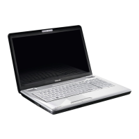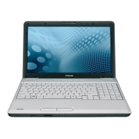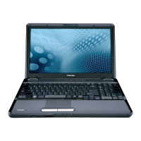
Do you have a question about the Toshiba Satellite L500D and is the answer not in the manual?
| Operating System | Windows Vista Home Premium |
|---|---|
| Chipset | AMD M780G |
| LAN | 10/100 Ethernet |
| Battery | 6-cell Lithium-ion |
| RAM | Up to 4GB DDR2 |
| Storage | 500GB HDD |
| Display | 15.6-inch (1366x768) |
| Graphics | ATI Radeon HD 3200 Graphics |
| Weight | 2.5 kg |
| Optical Drive | DVD SuperMulti |
| Wireless | Wi-Fi 802.11b/g |
| Ports | VGA, HDMI, RJ-45 |
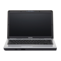
Describes the key features of the Toshiba Satellite L500/L500D notebook computer.
Details the specifications and characteristics of the 2.5-inch Hard Disk Drive.
Describes the capabilities and specifications of the DVD Super Multi drive.
Explains the functions and operation of the computer's power supply unit.
Details the types of batteries used in the computer and their specifications.
Introduces the chapter's scope, covered FRUs, diagnostic disk, and necessary tools.
Provides a guide for determining troubleshooting procedures based on problem symptoms.
Details steps to diagnose and resolve issues related to the computer's power supply.
Outlines procedures to determine if the computer's display is functioning properly.
Provides steps to diagnose and resolve problems with the computer's keyboard.
Guides on diagnosing and resolving issues with external USB devices.
Details procedures for diagnosing and resolving problems with the built-in TouchPad.
Outlines steps to determine if the computer's built-in speakers are functioning correctly.
Provides procedures to diagnose and resolve issues with the computer's wireless LAN system.
Guides on diagnosing and resolving faults related to the computer's internal camera.
Details procedures for diagnosing and resolving problems with the computer's Bluetooth functionality.
Outlines steps to determine if the 3-in-1 card reader is functioning properly.
Provides procedures to diagnose and resolve issues with the computer's Hard Disk Drive or Solid State Drive.
Guides on diagnosing and resolving issues related to the computer's CRT port.
Details procedures to diagnose and resolve problems with the computer's LAN port.
Outlines steps to diagnose and resolve issues with the computer's microphone.
Provides procedures to diagnose and resolve problems with the computer's buttons.
Guides on diagnosing and resolving issues with the computer's modem.
Outlines steps to diagnose and resolve issues with the Express card slot.
Guides on diagnosing and resolving issues with the computer's HDMI port.
Details procedures to diagnose and resolve issues with the computer's E-SATA system.
Outlines steps to determine if the computer's internal optical drive is functioning properly.
Explains how to use the Test & Diagnostic program to test hardware module functions.
Provides steps to start and run the DIAGNOSTICS PROGRAM using a USB disk.
Shows the unit configuration, including CPU type, memory size, and panel details.
Allows users to confirm speaker functions by playing music during the test.
Tests whether the computer's fan is working by listening for sound or feeling airflow.
Shows and measures the main battery's type, manufacturer, capacity, and charge function.
Tests the Floppy Disk Drive, including sequential seek, funnel code, and write/read functions.
Checks computer memory frequency and size for each slot.
Tests the functionality of all keys on the keyboard.
Allows users to test Touch Pad buttons, speed, acceleration, and assignments.
Checks video display quality in Text and VGA modes for pixel defects.
Tests the magnetic function that turns off the display when the LCD cover is closed.
Checks the LAN full-duplex environment and includes subtests for speed.
Checks the computer's RTC and calendar functions by comparing DOS and CMOS values.
Tests the functionality of specific button SKUs.
Verifies the functionality of the first Hard Disk Drive.
Allows checking Toshiba Part No., Serial No., Product Name, OEM string, and UUID.
Allows writing OEM string, version, serial, and product information to DMI.
Explains how to disassemble the laptop and replace Field Replaceable Units (FRUs).
Lists DANGER and WARNING precautions for disassembly and component handling.
Details preparations, tools, working environment, and component handling before disassembly.
Lists necessary tools and equipment for disassembly and reassembly, including ESD protection.
Specifies torque values for securing screws to prevent damage.
Covers battery removal and installation procedures.
Details procedures for removing and installing the Hard Disk Drive.
Covers procedures for removing and installing optional memory modules.
Details procedures for removing and installing the Optical Disk Drive bay module.
Covers procedures for removing and installing the keyboard cover and keyboard.
Details procedures for removing and installing the WLAN card.
Covers procedures for removing and installing the logic upper assembly.
Details procedures for removing and installing the power board.
Covers procedures for removing and installing the touch pad button board and bracket.
Details procedures for removing and installing the thermal fan.
Covers procedures for removing and installing the motherboard.
Details procedures for removing the thermal module and VGA board.
Covers procedures for removing and installing the CPU.
Details procedures for removing and installing the modem card.
Covers procedures for removing and installing the speakers.
Details procedures for removing and installing the display assembly.
Covers procedures for removing and installing the LCD bezel assembly.
Details procedures for removing the LCD module and inverter board.
Covers procedures for removing and installing the CMOS board and MIC.
Details procedures for removing and installing the USB board.
Covers procedures for removing and installing the Bluetooth card.
Provides precautions for handling the LCD module to prevent damage.
Details the layout of the system board with ICs and connectors.
Lists pin assignments for various connectors on the system board.
Provides scan codes and character mapping for keyboard keys.
Shows keyboard layouts for different languages and regions.
Lists screw specifications and torque values for assembly.
Shows Mean Time Between Failures (MTBF) for various components.
