2-2
Screws (1)
Rear panel (2)
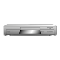
1-1-4. Tray
1. Pull out the tray (1) towards you until it stops.
2. Lift up claw A with a minus screwdriver, and pull out
the tray (1) towards you, then remove the tray (1).
Fig. 2-1-5
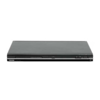
1-1-5. Rear Panel
1. Remove six screws (1) and remove the rear panel (2).
Fig. 2-1-6
Tray
panel (2)
Tray (1)
Tray (1)
Tray
Panel (2)
Claw
Claw
A
A
B
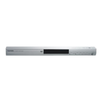
<Tray Panel Removal>
1. Eject the tray (1). (Refer to item 1-1-2.)
2. Twist the tray panel (2) a little in the arrow A direction
with the tray (1) hold by hand to release two claws and
lift up the tray panel (2) in the arrow B direction, then
the tray panel (2) is removed.
3. When mounting the tray panel (2), insert the tray panel
(2) along the grooves of the both sides of the tray (1)
until clicking.
Front
panel (2)
Claws
Claw
Flexible
cable (1)
Claw
Fig. 2-1-3
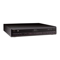
1-1-3. Front Panel
1. Remove one flexible cable (1).
2. Release four claws and remove the front panel (2).
Fig. 2-1-4
Mechanism
chassis assembly
Tray (1)
Pull out the tray (1)
toward you.
Tray (1)
Minus screwdriver
Claw A
Minus
screwdriver
 Loading...