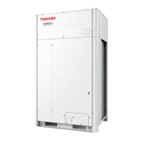
Do you have a question about the Toshiba SMMS-u MMY-MUP0801HT8 and is the answer not in the manual?
| Model | MMY-MUP0801HT8 |
|---|---|
| Series | SMMS-u |
| Cooling Capacity (kW) | 22.4 |
| Heating Capacity (kW) | 25.0 |
| Refrigerant | R410A |
| Outdoor Unit Noise Level | 56 dB(A) |
| Type | VRF |
| Power Supply | 380-415V, 50Hz |
Lists main parts for MMY-MUP***1HT8 outdoor units with models and specifications.
Details components and models for the inverter assembly.
Illustrates the physical placement of components within outdoor units for specific models.
Shows the physical layout of components within the inverter assembly for various models.
Details the layout and connections of the inverter's print circuit board.
Lists check codes on remote controllers, their causes, and countermeasures.
Addresses issues where the remote controller is unresponsive without displaying a check code.
Summarizes check codes detected by devices and provides troubleshooting analysis.
Provides troubleshooting information based on indoor unit indicators and check codes.
Details check codes on the 7-segment display and their verification locations.
Explains adjusting outdoor fan speed for high static pressure via DN code.
Describes settings for priority cooling, heating, or indoor unit operation modes.
Details optional control PC boards and their functions for outdoor units.
Explains the Notice Code function for caution and maintenance alerts.
Describes offsetting defrost timing between multiple connected systems.
Provides specifications for optional connectors on the indoor unit's P.C. board.
Explains how to perform a test operation check for individual indoor unit functions.
Details functions for checking refrigerant connections and performing service operations.
Describes forcing PMV open/close on indoor units via switch operations.
Explains forcing PMVs and solenoid valves open/closed on outdoor units for testing.
Details checking outdoor fan operation and speed control via interface P.C. board switches.
Identifies abnormal outdoor units by forced fan operation.
Explains manual adjustment of TO sensor value for emergent operation.
Describes refrigerant leak detection using interface P.C. board switches.
Explains switching to service monitor mode for checking system status via remote controller.
Shows how to display system info like HP, unit counts, and modes on the header unit.
Details displaying outdoor unit info like check codes, HP, and compressor status.
Explains displaying outdoor cycle data like pressure and temperature sensor readings.
Describes displaying outdoor cycle data for follower units via the header unit display.
Shows displaying indoor unit info like check codes and HP on the header unit.
Explains displaying EEPROM check codes for outdoor units after power reset.
Provides characteristics and resistance values for various outdoor unit temperature sensors.
Lists temperature sensor characteristics and resistance values for indoor units.
Details corrective refrigerant amounts based on indoor unit horsepower and capacity.
Explains how system diversity affects the corrective refrigerant amount.
Provides prerequisites and information for using the Wave Tool Advance application.
Explains the application's reliance on NFC and smartphone alignment.
Details settings for enabling or disabling test operations via the WTA App.
Provides steps to confirm NFC tag communication if smartphone reading fails.
Specifies maximum allowable lengths and height differences for refrigerant piping.
Outlines restrictions on outdoor unit combinations and indoor unit connections.
Presents schematic diagrams of refrigerant flow for cooling and heating operations.
Shows the refrigerant flow path during cooling operation for header and follower units.
Illustrates the refrigerant flow path during heating operation for header and follower units.
Depicts the refrigerant flow during individual defrost cycles.
Shows refrigerant flow during automatic emergency cooling.
Illustrates refrigerant flow during manual emergency cooling.
Details the refrigerant flow path during the reclaim process.
Provides a schematic of refrigerant piping for specific outdoor unit models.
Schematic of refrigerant piping for 8, 10, 12, and 14 HP outdoor units.
Schematic of refrigerant piping for 14A, 16, 18, and 20 HP outdoor units.
Schematic of refrigerant piping for 22 and 24 HP outdoor units.