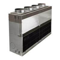
Do you have a question about the Toshiba RAV-SM803AT-E and is the answer not in the manual?
Explanation of indications and illustrated marks for user safety during operation and maintenance.
Precautions for R410A refrigerant safety, installation, service, and pipe materials.
Lists required and general tools for R410A installation and service.
Detailed specifications for various indoor unit types, including Digital and Super Digital Inverter models.
Detailed specifications for Digital and Super Digital Inverter outdoor units.
Graphs showing compressor speed vs. current for Digital and Super Digital Inverter models.
Static pressure characteristics for various concealed duct models.
External views and dimensions for 4-Way Air Discharge Cassette, Concealed Duct, and Under Ceiling types.
External views and dimensions for Digital and Super Digital Inverter outdoor units.
Wiring diagrams for 4-Way Air Discharge Cassette, Concealed Duct, and Under Ceiling indoor units.
Wiring diagrams for Digital Inverter outdoor units.
Lists electrical parts for 4-Way Air Discharge Cassette, Concealed Duct, and Under Ceiling indoor units.
Lists electrical parts for Digital Inverter outdoor units.
Details on optional accessory parts like drain up kits and ceiling panels.
Safety precautions, installation, servicing, and refrigerant piping guidelines for R410A.
Guidelines for processing copper pipes, including flare and socket joint procedures.
Detailed procedures and dimensions for flare processing and nut dimensions for R410A and R22.
Precautions and torque values for connecting flare surfaces correctly.
Steps for recharging refrigerant, including recovery, vacuuming, and charging procedures.
Materials for brazing, reasons for flux, and characteristics of flux.
Brazing procedures to prevent oxidation, types of flux, and piping materials.
Instructions and conditions for reusing existing R22/R407C refrigerant piping with R410A models.
Checks for scratch/dent, oil condition, and pipe compatibility when reusing existing pipes.
Procedures for recovering refrigerant from specific outdoor unit models.
Block diagram illustrating the indoor unit's control circuit and components.
Details on unit reset, operation mode selection, and temperature control.
Specifications for automatic capacity control and air speed selection.
Specifications for heating fan control, cool air discharge preventive control, and freeze preventive control.
Specifications for high-temperature release control and defrost control.
Specifications for drain pump control, after-heat elimination, and louver control.
Specifications for test run operations and filter reset signal display.
Specifications for central control mode, energy-saving control, and louver position.
Specifications for maximum frequency cut control and DC motor operation.
Diagram and identification of components on the indoor P.C. board (MCC-1402).
Specifications for optional connectors on the indoor P.C. board.
Comparison table of P.C. boards for Digital Inverter models.
List of check codes detected by indoor and outdoor units, with causes and measures.
Error modes detected by LEDs on the outdoor P.C. board.
Step-by-step troubleshooting procedures for specific error codes like E01, E09, E04, etc.
Graphs showing the relationship between temperature sensor resistance and temperature.
Procedures for replacing the indoor P.C. board, including EEPROM data handling.
Procedure for test run setup on remote controllers (wired and wireless).
Instructions for cabling and setting wired and wireless remote controllers as sub-units.
How to use the remote controller's monitor function to check sensor temperatures.
Function, wiring, and P.C. board switch setup for TCC-LINK adapter for central control.
Procedure for manually setting indoor unit addresses using the remote controller.
Terminology, system configurations, and automatic address examples for group control.
Procedures for detaching and attaching parts of the indoor unit.
Exploded views and part lists for 4-Way Air Discharge Cassette, Concealed Duct, and Under Ceiling indoor units.
Exploded views and part lists for Digital Inverter outdoor units.
Procedures for replacing drain up kit components.
Recommendations for parts and tools required for cord heater installation.
Step-by-step procedures for installing the cord heater, including cabinet and component removal.
Important warnings and guidelines regarding refrigerant leakage and concentration limits.
| Brand | Toshiba |
|---|---|
| Model | RAV-SM803AT-E |
| Category | Air Conditioner |
| Language | English |


 Loading...