Do you have a question about the Toshiba RAV-SM800BT-E and is the answer not in the manual?
Details specifications for various indoor unit types, including cassette and duct models.
Details specifications for outdoor units, including models RAV-SM560AT-E and RAV-SM800AT-E.
Information on compatible combinations of indoor and outdoor units.
Graphs illustrating operational characteristics and capacity variations.
Characteristics of static pressure for different models related to air ducting.
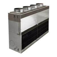
External views and construction details of Indoor Units, covering cassette and duct types.
External views and construction details of Outdoor Units.
Diagram showing the refrigerating cycle connecting indoor and outdoor units.
Wiring diagrams for various indoor unit types, including cassette, duct, and under-ceiling.
Wiring diagrams for outdoor units.
Specifications for electrical components within indoor units.
Specifications for electrical components within outdoor units.
Specifications for accessory parts sold separately.
Essential safety precautions for R410A refrigerant handling.
Guidelines for installing refrigerant piping, including materials and processing.
List of tools required for R410A refrigerant handling and installation.
Procedure for safely recharging refrigerant according to specifications.
Procedures and materials for brazing refrigerant pipes.
Block diagram of the indoor unit's control circuit and its components.
Detailed specifications for various control functions and modes.
General troubleshooting overview and initial checks for wired and wireless remote controllers.
Table of error codes detected by the indoor unit, with causes and measures.
Error modes detected by the outdoor unit, including LED indicators and check codes.
Step-by-step procedures for diagnosing and resolving various error codes and issues.
Guidelines for replacing the indoor P.C. board, including data readout and writing.
Instructions for initial setup of indoor units, including test runs and function selection.
Installation and configuration procedures for the network adapter.
Methods for setting network addresses for indoor units and group control.
Comparison of displays and operations between main and central remote controllers.
Manual procedure for setting indoor and outdoor unit addresses.
Steps for setting addresses and configuring group control systems.
Detailed steps for manual address setup via the remote controller.
Step-by-step guides for disassembling and reassembling indoor unit components.
Procedures for disassembling and attaching parts of the outdoor unit.
Illustrated breakdown of indoor unit components with part numbers.
Illustrated breakdown of outdoor unit components with part numbers.
Recommended parts list for cord heater installation work.
| Brand | Toshiba |
|---|---|
| Model | RAV-SM800BT-E |
| Category | Air Conditioner |
| Language | English |