


E
edwardsstephenAug 5, 2025
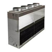
Why does my Toshiba RAV-SM802KRT-E flash alternatively?
- DDuane FloresAug 5, 2025
If your Toshiba Air Conditioner flashes alternatively, it indicates that a protective device in either the outdoor or indoor unit is active. You should check both the outdoor and indoor units to determine which protective device is causing the issue.