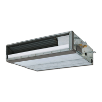
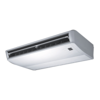
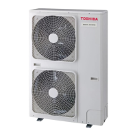
Do you have a question about the Toshiba RAV-SM804UTP-E (TR) and is the answer not in the manual?
Defines who is qualified to install, repair, and maintain air conditioners based on knowledge and qualifications.
Details protective gear required for various work tasks and explains safety symbols used in the manual.
Confirms labels on the air conditioner unit and their associated meanings for safe operation.
Lists critical safety warnings related to electrical hazards and proper shutdown procedures for safe operation.
Details specific actions that are prohibited to prevent hazards during operation or maintenance.
Provides general warning statements regarding refrigerant handling, electrical work, and working at heights.
Outlines warnings about handling heavy objects and potential injuries from moving parts and electrical components.
Details safety measures for handling refrigerants like R410A and potential risks associated with them.
Emphasizes safety during assembly, insulation testing, and checks performed after repair work.
Highlights specific safety precautions when working with the new R410A refrigerant.
Lists required tools and initial confirmation points before starting troubleshooting procedures.
Provides an overview of the troubleshooting procedure, including confirmation and checking steps.
Details troubleshooting procedures specific to the wireless remote controller.
Explains how to interpret lamp indications and check codes for diagnosing unit issues.
Lists specific check codes related to indoor and outdoor unit errors and their causes.
Provides a comprehensive list of check codes for indoor units and their diagnostic procedures.
Explains error modes detected by the diagnostic function and corresponding measures.
Details error modes related to remote and central controllers, including TCC-LINK communication.
Provides step-by-step diagnostic procedures for E01 and E09 error codes.
Outlines diagnostic steps for E04 and E10 error codes.
Provides diagnostic procedures for E18, L03, L07, L08, and L09 error codes.
Details diagnostic steps for L20, L30, and P30 error codes.
Outlines diagnostic procedures for P10 and F10 error codes.
Provides step-by-step diagnostic and troubleshooting for the P12 error.
Details diagnostic steps for the P19 error and operation checks for the outdoor PC board.
Provides troubleshooting steps for F02 (TC sensor) and F01 (TCJ sensor) errors.
Outlines the diagnostic procedure for the C06 error related to 1:1 model connection.
Explains the causes and behaviors of E03, F29, and P31 errors in the air conditioning system.
Explains how to read out EEPROM data before replacing the P.C. board.
Outlines the procedure for setting addresses for indoor units in group operation.
Guides on manually setting indoor unit addresses using the remote controller.
| Cooling Capacity | 8.0 kW |
|---|---|
| Heating Capacity | 9.0 kW |
| Seasonal Energy Efficiency Ratio (SEER) | 6.1 |
| Seasonal Coefficient of Performance (SCOP) | 4.0 |
| Power Supply | 220-240V, 50Hz |
| Refrigerant | R410A |
| Outdoor Unit Noise Level | 51 dB(A) |
| Type | Split Type |


