Do you have a question about the Toshiba RAV-SM1404UTP-E (TR) and is the answer not in the manual?
Covers essential safety precautions for electrical hazards, prohibition, and protection during operation.
Covers safety related to modification, specified parts, fire, and refrigerant handling.
Lists required tools and initial confirmation points before commencing troubleshooting procedures.
Outlines the systematic procedure for diagnosing and resolving issues based on signal lamp indications.
Details error causes and checks based on various lamp indications like Operation, Timer, Ready, and Flash.
Lists specific error codes (F01-F31) and their corresponding causes and diagnostic checks.
Provides a comprehensive list of check codes for indoor units and their operational status confirmation.
Details diagnostic procedures and recommended measures for specific indoor unit error codes like E03, E04, E08, E10, E18.
Addresses error codes related to remote controllers and central control systems (E01, E02, E09, E18, P30).
Provides a flowchart for diagnosing and resolving E01 errors related to inter-unit cables and connections.
Offers diagnostic steps for E04 (group address) and E10 (communication error) issues.
Details troubleshooting for E18 (communication error) and E09 (capacity setting) errors.
Guides through diagnosing and resolving L20, L30, and P30 errors for central control and group operations.
Outlines diagnostic steps for P10 (float switch/drain pump) and F10 (TA sensor) errors.
Provides a flowchart for diagnosing and resolving P12 errors related to the fan motor.
Guides through diagnosing P19 errors related to the 4-way valve and its operation.
Details troubleshooting for F02 (TC sensor) and F01 (TCJ sensor) errors.
Addresses C06 errors related to 1:1 model connection interface and central controller setup.
Explains E03 (header indoor unit communication), F29 (EEPROM error), and P31 (follower unit error) troubleshooting.
Outlines two cases for PC board replacement and the general procedures involved.
Details how to read/write setting data from EEPROM and procedures for replacing the PC board for indoor units.
Guides through the process of writing configuration data to the EEPROM using the remote controller.
Outlines the step-by-step process for setting indoor unit addresses and group addresses.
Explains the importance of checking refrigerant concentration limits and the associated risks of leakage.
| Brand | Toshiba |
|---|---|
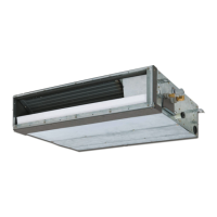
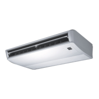
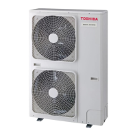
| Model | RAV-SM1404UTP-E (TR) |
| Category | Air Conditioner |
| Language | English |