EasyManua.ls Logo

Toshiba RAV-GM2801AT8-TR User Manual

Toshiba RAV-GM2801AT8-TR
114 pages
To Next Page IconTo Next Page
Page #1 background imageLoading...
Page #1 background image
PRINTED IN JAPAN, Mar., 2019, TOMO
FILE No. A10-1901
SERVICE MANUAL
AIR-CONDITIONER
SPLIT TYPE
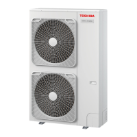
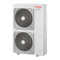
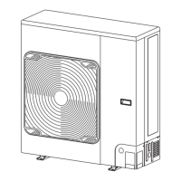
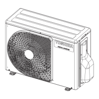
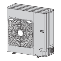
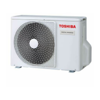
OUTDOOR UNIT
<DIGITAL INVERTER>
RAV-GM2241AT8-E RAV-GM2241AT8-TR
RAV-GM2801AT8-E RAV-GM2801AT8-TR
RAV-GM2241AT8J-E RAV-GM2241AT8J-TR
RAV-GM2801AT8J-E RAV-GM2801AT8J-TR

Table of Contents

Question and Answer IconNeed help?

Do you have a question about the Toshiba RAV-GM2801AT8-TR and is the answer not in the manual?

Toshiba RAV-GM2801AT8-TR Specifications

General IconGeneral
BrandToshiba
ModelRAV-GM2801AT8-TR
CategoryAir Conditioner
LanguageEnglish

Summary

Precaution for Safety

1. SPECIFICATIONS

3. OUTDOOR UNIT REFRIGERATING CYCLE DIAGRAM

4. WIRING DIAGRAM

6. REFRIGERANT R32

6-1. Safety During Installation/Servicing

Safety precautions for handling R32 refrigerant during installation and servicing.

6-4. Recharging of Refrigerant

Step-by-step procedure for recharging refrigerant into the air conditioning system.

6-8. General safety precautions for using R32 refrigerant

General safety measures for using R32 refrigerant, including recovery and decommissioning.

7. CIRCUIT CONFIGURATION AND CONTROL SPECIFICATIONS

8. TROUBLESHOOTING

8-1. Summary of Troubleshooting

Summary of troubleshooting steps and confirmation points for wired remote controllers.

8-2. Diagnostic Procedure for Each Check Code (Outdoor Unit)

Diagnostic methods for check codes displayed on wired remote controllers and LED indicators.

8-1-1. Monitor Function of Remote Controller

Check Code List

9. SETUP AT LOCAL SITE AND OTHERS

2. Service support functions (LED display and switch operation)

10. ADDRESS SETUP

11. REPLACEMENT OF THE SERVICE P.C. BOARD

11-1. Interface (CDB) P.C. BOARD MCC-1675 (4316V693)

Instructions for replacing the Interface (CDB) P.C. Board, including jumper settings.

11-2. Compressor IPDU P.C. BOARD MCC-1698 (4316V624)

Instructions for replacing the Compressor IPDU P.C. Board.

12. HOW TO EXCHANGE COMPRESSOR

12-1. Exchanging Procedure of Compressor (Outline)

An outline of the steps involved in exchanging the compressor.

Electrical part replacement

Electrical part replacement (continued)

Fan motor

Compressor and compressor lead

1. Removing a broken compressor

Step-by-step procedure for removing a faulty compressor, including safety warnings.

Compressor and compressor lead (continued)

2. Compressor attachment

Procedure for attaching a new compressor, including lead winding and sound insulation.

3. Vacuum

Steps for vacuuming the system after compressor replacement, including electronic control valve operation.

4. Refrigerant encapsulation

Procedure for adding refrigerant based on pipe length.

14. EXPLODED VIEWS AND PARTS LIST

14-2. Inverter Assembly

Related product manuals