Do you have a question about the Toshiba RAV-GM2241AT8-TR and is the answer not in the manual?
| Brand | Toshiba |
|---|---|
| Model | RAV-GM2241AT8-TR |
| Category | Air Conditioner |
| Language | English |
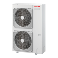
Details technical specifications for the outdoor unit, including power, dimensions, and performance data.
Presents operational curves for cooling and heating based on compressor speed and outdoor temperature.
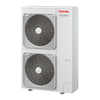
Illustrates external dimensions and component layout of the outdoor unit with labeled parts.
Detailed wiring schematic for the outdoor unit, including component connections and terminal assignments.
Lists electrical components used in the outdoor unit with their part numbers, types, and specifications.
Safety precautions and essential considerations for installing and servicing R32 refrigerant.
Guidelines for installing refrigerant piping, including material selection, processing, and joint types.
Details on suitable copper pipe materials and joint types for R32 refrigerant.
Provides an overview and initial checks for troubleshooting common issues.
Guides for diagnosing outdoor unit faults using check codes and LED indicators.
Provides resistance value characteristics for various sensors used in the system.
Procedure to access and view past trouble codes recorded by the system.
Instructions for accessing outdoor unit status and operations via service switches.
Step-by-step guide for setting up unit addresses for proper communication.
Defines terms and explains system configurations for group and individual unit addressing.
Details wiring diagrams and guidelines for connecting remote controllers to indoor units.
Manual method for setting unit addresses directly from the remote controller.
Methods to verify the assigned addresses of indoor units.
Instructions for replacing the Interface (CDB) P.C. board, including jumper settings.
Guidance on replacing the Compressor IPDU P.C. board, including switch settings.
An outline of the steps involved in replacing the compressor.
Refers to section 13 for detailed compressor exchange procedures.
Exploded view diagrams and a parts list for the outdoor unit.
Exploded view diagrams and a parts list for the inverter assembly.