Do you have a question about the Toshiba RAV-GM1101AT8P-E and is the answer not in the manual?
Defines qualifications and knowledge for installation and service personnel.
Details protective gear required for different types of work.
Explains warning labels and symbols displayed on the unit.
Specific safety warnings for imminent danger causing death or serious injury.
Safety warnings indicating risk of death or serious injury from product troubles.
General safety precautions and guidelines for installation and service.
List of tools required for R410A/R32 installations, indicating applicability.
Common tools required for installation and maintenance tasks.
Technical specifications for the outdoor unit, including dimensions and power.
Curves showing compressor speed vs. current and capacity variation.
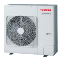
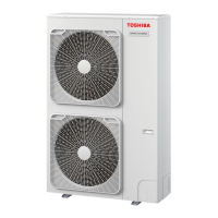
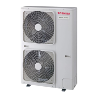
External views and dimensions of the outdoor unit models.
Diagrams of refrigerating cycles for single and twin indoor units.
Diagram of the outdoor unit's refrigerating cycle components.
Wiring diagram for the outdoor unit models.
List of electrical parts used in the outdoor unit and their specifications.
Safety precautions specific to R32 refrigerant during installation and service.
General safety guidelines for installation and service with R32 refrigerant.
Details on copper pipes, joints, and their specifications for R32.
Step-by-step procedure for recharging refrigerant into the system.
Procedures and materials for brazing refrigerant pipes.
Guidelines for reusing existing R22/R407C piping for R32 installations.
Precautions and limits for adding refrigerant to a system.
General safety measures for using R32 refrigerant.
Explanation of the outdoor unit's control system and circuit boards.
Overview of main control functions like PMV, discharge temp. control, fan control.
General guidelines and required tools for troubleshooting issues.
Detailed troubleshooting steps based on error codes and lamp indications.
A list of outdoor unit check codes, their causes, and indications.
Flowcharts for diagnosing specific outdoor unit error codes.
Procedure to measure resistance values of compressor windings.
Procedure to measure resistance values of the outdoor fan motor.
Procedure to retrieve and view past error history from the indoor unit.
Steps for setting up addresses for group control operation.
Procedures for detaching and attaching major external parts.
Exploded view of the outdoor unit with numbered parts.
Guidelines for refrigerant concentration limits in installation rooms.
| Brand | Toshiba |
|---|---|
| Model | RAV-GM1101AT8P-E |
| Category | Air Conditioner |
| Language | English |


