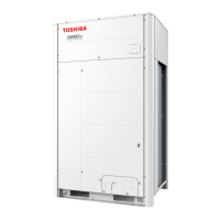
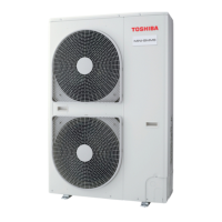
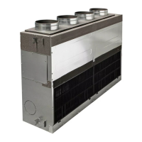
Do you have a question about the Toshiba MiNi-SMMS MCY-MAP0501HT and is the answer not in the manual?
Discusses the concentration limit for refrigerant gas in rooms and necessary precautions.
Wiring diagram for 4-way air discharge cassette indoor units.
Wiring diagram for 2-way air discharge cassette indoor units.
Wiring diagram for 1-way air discharge cassette indoor units.
Wiring diagram for 1-way air discharge cassette type indoor units.
Wiring diagram for concealed duct standard type indoor units.
Instructions and precautions for installing the air conditioner unit.
Guidelines for maintenance, including air filter cleaning and safety.
Troubleshooting guide for common symptoms and their causes.
Illustrates the refrigerant flow and components in the system.
Details the power peak-cut control feature and its wiring.
Explains the external master ON/OFF control function and its wiring.
Describes the night operation sound reduction control and its function.
Details the operation mode selection control using SMC or SMH signals.
Explains the operation and error monitoring using the error output control board.
Outlines the general procedure for test operations.
Lists essential checks before performing a test operation, covering electric wiring and system connections.
Procedure for setting up indoor unit addresses, including automatic and manual methods.
Common issues encountered during test operation and their solutions.
Specific checks for fan operation and cooling/heating test operations.
Explains various service support functions controllable from the outdoor unit.
Procedures for clearing errors from the remote controller or interface P.C. board.
Provides a summary of common troubles and necessary tools for diagnosis.
Explains how to identify faults using check codes displayed on remote or interface P.C. boards.
Guides troubleshooting based on check codes displayed on the wired remote controller.
Lists check codes and their detected positions for troubleshooting.
Detailed diagnostic flowcharts for various check codes to identify faults.
Explains how to interpret the 7-segment display on the outdoor unit's interface P.C. board for troubleshooting.
Details Pd and Ps sensor output characteristics and voltage checks for the outdoor unit.
Describes the methods for backup operation based on different trouble types.
Provides an outline for the compressor replacement procedure, including safety warnings.
Details vacuuming procedures and full opening of PMV for compressor replacement.
Detailed procedure for replacing the compressor, including oil amount calculation.
| Model | MCY-MAP0501HT |
|---|---|
| Category | Air Conditioner |
| Heating Capacity | 5.6 kW |
| Refrigerant | R410A |
| Cooling Capacity | 5.0 kW |
| Power Supply | 220-240 V, 50 Hz |
| Outdoor Unit Noise Level | 50 dB |
