EasyManua.ls Logo

Toshiba T1950CT User Manual

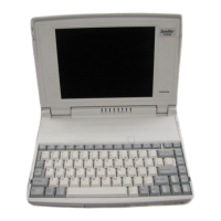
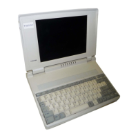
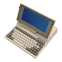
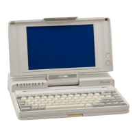
Toshiba T1950CT
184 pages
To Next Page IconTo Next Page
Page #1 background imageLoading...
Page #1 background image
1-1
1.1 Features
The T1950, T1950CS and T1950CT units consist of the following features.
Processor Intel SL-Enhanced 486DX2/40Mhz. (P24S chip)
Processor Type DX2: (3.3v w/8KB internal cache) Co-processor embedded.
BIOS 128KB flash EPROM (150ns)
RAM 4MB Expandable to 20MB (80ns)
Display T1950: Fluorescent Sidelit Monochrome LCD
T1950CS: Dynamic-STN Dual Scan Color LCD
T1950CT: TFT Active Matrix Color LCD
Ext. Display T1950 & T1950CS: VGA 640 x 480 (16 colors of 4096)
T1950CT: 800 x 600/256 colors;1024 x 768/256 colors
(using Toshiba supplied drivers)
FDD 3 1/2" 1.44MB
HDD T1950 & T1950CS: 120MB/200MB
T1950CT: 200MB/320MB
Optional Peripherals 101-key Keyboard (PS/2)
1 - 14.5mm PCMCIA Type III (2.0)
Ports 1 9-PIN Serial (16450 UART)
1 Parallel/FDD: BI-DIR
1 15-PIN RGB
1 Mouse Quick Port (DCBM)
1 PS/2 Mouse Port (not usable if DCBM connected)
Keyboard 1 101-key Keyboard Port (PS/2)
82-Keys, 3mm Travel
Battery NIMH (12V 2400mAH) PART# PA2420UXRA
Battery Life 2-3 HRS.
Recharge Time 1.4-2.3 HRS (Computer off only)
AC Adapter T1950 & T1950CS: Input: 100-240VAC , Input Frequency:
50-60Hz, Input Power: .5A - .28A (50/60Hz)
Output Voltage: 18 VDC, 1.1A
T1950CT: Input: 100-240VAC, Input Frequency: 50-60Hz,
Input Power: .7A - .4A (50/60Hz)
Output Voltage: 18 VDC, 1.7 A
Bundled Software Toshiba DOS 6.0; Windows 3.1; MaxTime; Ultrafont.
Dimensions T1950: 11.7"W x 8.4"D x 2.0"H, 6.4 lbs.
T1950CS & T1950CT: 11.7"W x 8.4"D x 2.1"H, 7 lbs.

Table of Contents

Question and Answer IconNeed help?

Do you have a question about the Toshiba T1950CT and is the answer not in the manual?

Toshiba T1950CT Specifications

General IconGeneral
ProcessorIntel 486SX
RAM4 MB
Maximum RAM20MB
Storage120 MB HDD
Resolution640 x 480
Battery Life2-3 hours
Display9.5-inch
Operating SystemMS-DOS
Floppy Drive3.5 in
PortsSerial, Parallel, VGA
Screen TypeTFT

Summary

Features

System Unit Block Diagram

3.5-inch Floppy Disk Drive

2.5-inch Hard Disk Drive

Keyboard

Monochrome LCD (T1950)

Monochrome LCD Module

Details specifications and function of the monochrome LCD.

Monochrome Fluorescent Lamp (FL) Inverter Board

Provides specifications for the FL inverter board.

STN Color LCD (T1950CS)

STN Color LCD Module

Details specifications and function of the STN color LCD.

STN Color Fluorescent Lamp (FL) Inverter Board

Provides specifications for the STN FL inverter board.

TFT Color LCD (T1950CT)

TFT Color LCD Module

Details specifications and function of the TFT color LCD.

TFT Color Fluorescent Lamp (FL) Inverter Board

Provides specifications for the TFT FL inverter board.

Power Supply

Batteries

Battery Indicator

Explains the battery indicator colors and status meanings.

Main Battery

Describes the main battery's role and recharge function.

Battery Charging Control

Details battery charging control and charging times.

Backup Battery

Explains backup battery maintenance and charging.

RTC Battery

Explains the RTC battery's function and charging time.

Troubleshooting

Troubleshooting Flowchart

Provides a flowchart for diagnosing computer issues.

Power Supply Troubleshooting

Checks power supply issues via LED indicators and replacement.

System Board Troubleshooting

Guides troubleshooting for system board defects.

Printer Port LED Check in Boot Mode

Uses printer port LEDs to check boot mode status.

Printer Port LED Check in Resume Mode

Uses printer port LEDs to check resume mode status.

Diagnostic Test Program Execution Check

Executes diagnostic tests from the diagnostic menu.

System Board Replacement Check

Guides replacement of system boards based on errors.

Floppy Disk Drive Troubleshooting

Guides troubleshooting for floppy disk drive issues.

FDD Head Cleaning Check

Details the FDD head cleaning procedure.

External 5.25-inch FDD Check

Checks the system with an external FDD.

Diagnostic Test Program Execution Check

Executes FDD diagnostics and checks error codes.

Connector Check and Replacement Check

Checks FDD cable connections and replaces components.

Hard Disk Drive Troubleshooting

Guides troubleshooting for hard disk drive issues.

Partition Check

Checks HDD partition information using FDISK.

Message Check

Checks for HDD error messages and system transfer.

Format Check

Guides the formatting process for the HDD.

Diagnostic Test Program Execution Check

Executes HDD diagnostics and checks error codes.

Keyboard Troubleshooting

Guides troubleshooting for keyboard issues.

Diagnostic Test Program Execution Check

Executes keyboard diagnostic tests.

Connector and Replacement Check

Checks keyboard cable and controller.

Display Troubleshooting

Guides troubleshooting for display issues.

Contrast Control Check

Checks display contrast and brightness controls.

External CRT Check

Connects an external CRT to test display functionality.

Diagnostic Test Program Execution Check

Executes display diagnostic tests.

Connector Check

Checks display unit cable connections.

Replacement Check

Guides replacement of display components.

The Diagnostic Test

Executing the Diagnostic Test

Subtest Names

System Test

Memory Test

Keyboard Test

Display Test

Floppy Disk Test

Printer Test

Async Test

Hard Disk Test

Real Timer Test

PCMCIA Test

Error Codes and Error Status Names

Hard Disk Test Detail Status

Hard Disk Format

Head Cleaning

Log Utilities

Running Test

Floppy Disk Drive Utilities

System Configuration

SETUP

General

The Battery Pack

Optional Memory Card

Optional PCMCIA Card

Top Cover

Keyboard

Hard Disk Drive Backup Battery

Display Mask

Display Assembly

Upper System Board

Lower System Board RTC Battery

Floppy Disk Drive and Mouse/KB Board

T1900C FL Inverter Board

T1900C LCD Module

T1900C Fluorescent Lamp (FL)

T1900 FL Inverter Board

T1900 LCD Module

T1900 Fluorescent Lamp (FL)

Appendix A Handling the LCD Module

Appendix B Board Layout

FATSU* Upper System Board

Shows the layout of the FATSU* upper system board.

FATSL* Lower System Board

Shows the layout of the FATSL* lower system board.

Appendix C Pin Assignments

PJ1 Memory Slot Connector (88-Pin)

Lists pin assignments for the 88-pin memory slot connector.

PJ2 RTC Connector (3-Pin)

Lists pin assignments for the 3-pin RTC connector.

PJ3 Mouse/KB Connector (10-Pin)

Lists pin assignments for the 10-pin Mouse/KB connector.

PJ4 KB I/F Connector (19-Pin)

Lists pin assignments for the 19-pin keyboard interface connector.

PJ5 (PJ501) Power Supply Interface Connector (40-Pin)

Lists pin assignments for the 40-pin power supply interface connector.

PJ7 LCD Connector 1 (20-Pin)

Lists pin assignments for the 20-pin LCD connector 1.

PJ8 LCD Connector 2 (10-Pin)

Lists pin assignments for the 10-pin LCD connector 2.

PJ9 CRT I/F Connector (15-Pin)

Lists pin assignments for the 15-pin CRT interface connector.

PJ10 (PJ206) Joint Connector (100-Pin)

Lists pin assignments for the 100-pin joint connector.

PJ11 Display Sensor Switch Connector (2-Pin)

Lists pin assignments for the 2-pin display sensor switch connector.

PJ201 PRT/FDD Connector (for Printer) (25-Pin)

Lists pin assignments for the 25-pin PRT/FDD connector.

PJ201 PRT/FDD (Ext) Connector (for FDD) (25-Pin)

Lists pin assignments for the 25-pin PRT/FDD (Ext) connector.

PJ202 Internal FDD Connector (26-Pin)

Lists pin assignments for the 26-pin internal FDD connector.

PJ203 Internal HDD Connector (44-Pin)

Lists pin assignments for the 44-pin internal HDD connector.

PJ204 Serial I/F Connector (9-Pin)

Lists pin assignments for the 9-pin serial interface connector.

PJ205 PC Card Slot Connector (68-Pin)

Lists pin assignments for the 68-pin PC Card slot connector.

PJ502 DC IN Connector (3-Pin)

Lists pin assignments for the 3-pin DC IN connector.

PJ503 Backup Battery Connector (2-Pin)

Lists pin assignments for the 2-pin backup battery connector.

PJ504 Main Battery Connector (5-Pin)

Lists pin assignments for the 5-pin main battery connector.

Appendix D USA Display Codes

Appendix E Keyboard Scan/Character Codes

Appendix F Keyboard Layouts

United States (US) Keyboard

Shows the layout of the US keyboard.

United Kingdom (UK) Keyboard

Shows the layout of the UK keyboard.

German (GR) Keyboard

Shows the layout of the German keyboard.

French (FR) Keyboard

Shows the layout of the French keyboard.

Spanish (SP) Keyboard

Shows the layout of the Spanish keyboard.

Italian (IT) Keyboard

Shows the layout of the Italian keyboard.

Scandinavian (SC) Keyboard

Shows the layout of the Scandinavian keyboard.

Swiss-German (SL) Keyboard

Shows the layout of the Swiss-German keyboard.

Canadian (Specialized) Keyboard

Shows the layout of the Canadian keyboard.

Appendix G Wiring Diagrams

Printer Wraparound Connector

Shows wiring for the printer wraparound connector.

RS-232-C Wraparound Connector

Shows wiring for the RS-232-C wraparound connector.

RS-232-C Direct Cable (9-Pin to 9-Pin)

Shows wiring for the RS-232-C direct cable.

Related product manuals