7-EN
System Configuration
Warning: Thermostat should be configured for conventional single or two stage systems
(Refer to Installation Steps and Wiring Example sections below).
Refer to the installation manuals supplied with the Indoor Unit, the Remote Controller, and the Thermostat
for any installation instructions.
1. All wiring should be Class 2.
2. All wiring shown below should be performed with AWG18 thermostat wire except between the Indoor Unit and the Remote Controller.
3. All wires to be used must satisfy all local and national regulations (Field procured).
4. The wiring between the Indoor Unit, the Remote Controller (optional), and the 24V Thermostat Interface should be performed with
AWG20 to AWG14 X 2. Limit the total length of the remote control wiring (L + L1) up to 980 ft (300 m).
5. W2 and Y2 signals are optional, and may be omitted when a single-stage thermostat is used.
Note: High/medium/low fan signals are optional, and may not be available on all thermostat models.
6. The Remote Controller is required during the start-up for address setting and diagnostics in case Error codes are shown.
Set the Remote Controller as “Follower remote control”. Refer to the Installation Manual of the Remote Controller for
instructions on configurations of the controller status.
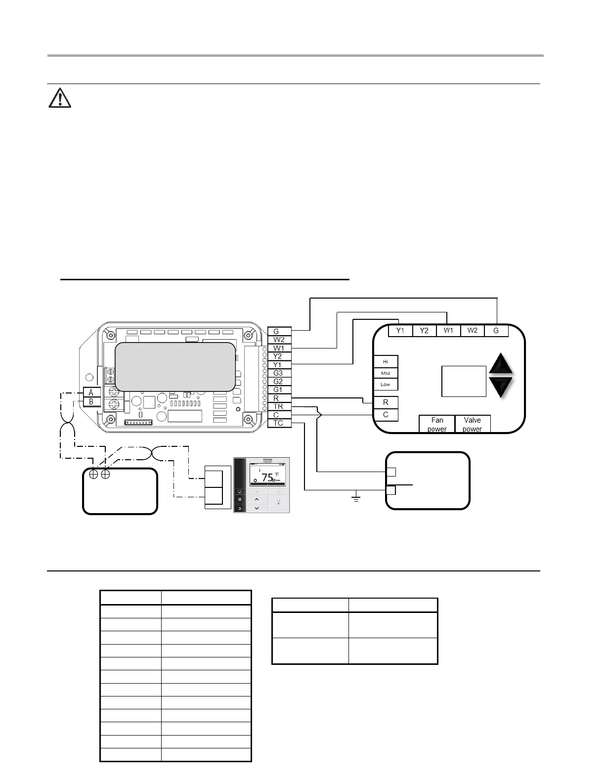
Basic wiring diagram: Single-stage Cooling and Heating
Terminal definition of 24V Thermostat Interface
Terminal definition
 Loading...