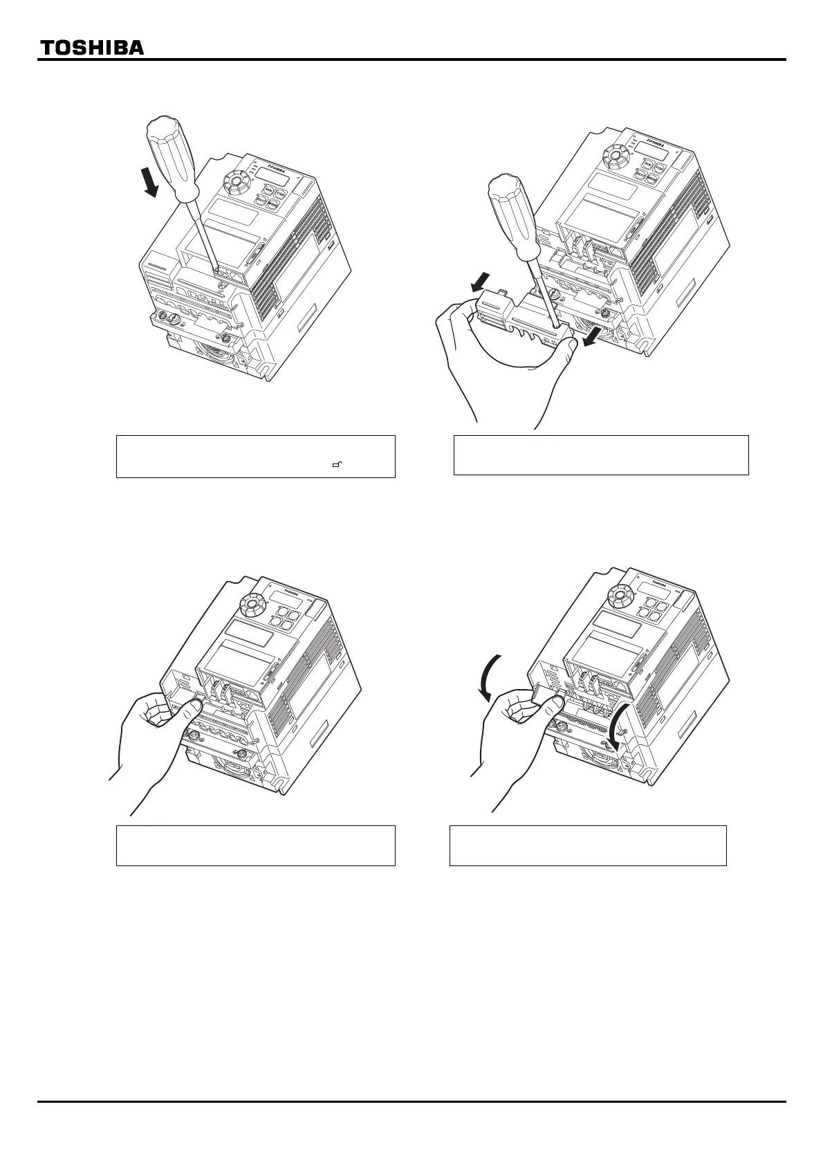
EasyManuals Logo

Toshiba TOSVERT VF-S15 series Instruction Manual Supplementary

Toshiba TOSVERT VF-S15 series
15 pages
To Next Page IconTo Next Page
To Previous Page IconTo Previous Page
Page #3 background imageLoading...
Page #3 background image
E6582185
3
1.3.2(3)外側端子台カバーはずし方
s2frev0101.eps
1.3.2(3)外側端子台カバーはずし方
s2frev0103.eps
1.3.2(4)内側端子台カバーのはずし方
s2frev0101.eps
EASY
R/L1
S/L2
T/L3
MODE
RUN
RUN
STATUS
PRG
MON
STOP
%
Hz
1.3.2(4)内側端子台カバーのはずし方
s2frev0102.eps
EASY
R/L1
S/L2
T/L3
MODE
RUN
RUN
STATUS
PRG
MON
STOP
%
Hz
(1) Removing the outside terminal block cover (VFS15-4004PL1-W1 to 4037PL1-W1)
(2) Removing the inside terminal block cover (VFS15-4004PL1-W1 to 4037PL1-W1)
After wiring is complete, be sure to restore the terminal cover to its original position.
1) 2)
Insert a screwdriver or other thin object
into the hole indicated with the mark.
While pressing on the screwdriver, sidles
the terminal cover downward to remove it.
1) 2)
The finger is put on to the tab part of the
terminal block cover.
While pressing on the finger,
rotate the
terminal cover downward to remove it.

Other manuals for Toshiba TOSVERT VF-S15 series

Questions and Answers:

Question and Answer IconNeed help?

Do you have a question about the Toshiba TOSVERT VF-S15 series and is the answer not in the manual?

Toshiba TOSVERT VF-S15 series Specifications

General IconGeneral
SeriesVF-S15
CategoryInverter
Control MethodV/f control, Sensorless vector control
Overload Capacity150% for 60 seconds
Protection FeaturesOvercurrent, Overvoltage, Undervoltage, Overheat, Short Circuit
Communication OptionsModbus
Braking UnitBuilt-in
Power Rating0.4 kW to 15 kW
Input VoltageSingle-phase 200 to 240V, Three-phase 200 to 240V, 380 to 480V
Cooling MethodFan cooling

Related product manuals