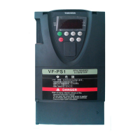
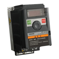
This document is an instruction manual for the VF-NC3C inverter, providing details on its connection, operation, parameter settings, and maintenance.
Function Description
The VF-NC3C is an inverter designed for controlling motor speed and operation. It offers various control modes, including V/F constant, variable torque, automatic torque boost, vector control, energy-saving, and V/F 5-point settings. It can be operated via a panel keypad or external signals, and supports communication via RS485. The inverter also includes protective functions such as electronic thermal overload protection, stall prevention, output phase failure detection, input phase failure detection, and over-torque trip.
Important Technical Specifications
- Input Voltage Class: 3-phase 400V class (380-460V, 50/60Hz).
- Applicable Motor (kW): Ranges from 0.4 kW to 11 kW, depending on the model (e.g., VFNC3C-4004P for 0.4 kW, VFNC3C-4110P for 11 kW).
- Output Current (A): Varies by model, e.g., 1.5 A for 0.4 kW motor, 24 A for 11 kW motor (rated output current at 4kHz or less).
- Output Voltage: 3-phase 380V to 460V, adjustable within 50V to 660V.
- Output Frequency Range: 0.1 Hz to 400.0 Hz.
- Overload Current Rating: 150% for 60 seconds, 200% for 0.5 seconds.
- PWM Carrier Frequency: Adjustable from 2 kHz to 12 kHz (default 4 kHz).
- Frequency Setting Resolution: 0.1 Hz for analog input (max. frequency 100 Hz), 0.01 Hz for panel and communication settings.
- Input Terminal Functions: Supports up to 5 programmable logic inputs, selectable between sink (negative) and source (positive) logic. Functions include forward/reverse run, preset speed commands (1-15 steps), jog run, emergency stop, DC braking, 2nd acceleration/deceleration, and V/F control mode switching.
- Analog Input: 0-10Vdc, 0-5Vdc, or 4-20mAdc for frequency command, with 1/1000 resolution.
- Output Terminal Functions: Supports up to 2 programmable open collector outputs and 1 relay contact output. Functions include low-speed signal, output frequency attainment, fault signal, over-current/overload pre-alarm, over-voltage pre-alarm, small current detection, over-torque detection, and parts replacement alarm.
- Communication: Built-in 2-wire RS485 communication, supporting baud rates of 9600, 19200, and 38400 bps.
- Protection Method: IP20.
- Cooling Method: Self-cooling or forced air-cooled, depending on the model.
Usage Features
- Standard Connections: Detailed wiring diagrams are provided for both SINK (negative) and SOURCE (positive) logic configurations, including connections for main circuit power, motor, braking resistors, and control signals.
- Setup Menu: Allows configuration of various parameters, including region codes (Europe, North America, Asia/Oceania, Japan) which automatically set default values for maximum frequency, frequency settings, VI input point 2 frequency, base frequency voltage, and sink/source switching.
- Simplified Operation: Users can select command mode (panel keypad, terminal board, RS485) and frequency setting mode (setting dial, external signals) for run/stop and frequency control.
- Frequency Setting: Can be set using an external potentiometer (1k-10kΩ), voltage input (0-10Vdc, 0-5Vdc), or current input (4-20mAdc).
- Acceleration/Deceleration: Offers manual settings for acceleration and deceleration times (0.0-3000 s) and automatic adjustment based on load size. S-pattern acceleration/deceleration is also available for smoother operation.
- Torque Boost: Manual and automatic torque boost functions are available to improve starting torque, especially at low speeds. Vector control and energy-saving modes also contribute to optimized torque.
- Preset Speed Operation: Up to 15 preset speeds can be programmed and selected via external logic signals.
- DC Braking: Allows application of direct current to the motor for strong braking torque, with adjustable starting frequency, current, and time.
- Jump Frequency: Helps avoid mechanical resonance by skipping specific frequency ranges during operation.
- PWM Carrier Frequency: Adjustable to change the tone of magnetic noise from the motor and reduce electromagnetic noise. Random mode is also available.
- Trip-less Intensification: Features like auto-restart after momentary power failure and regenerative power ride-through control ensure continuous operation. A retry function automatically resets the inverter after an alarm.
- Output Voltage Adjustment/Supply Voltage Correction: Parameters allow adjustment of output voltage and correction for input voltage fluctuations to maintain a constant V/F ratio.
- Reverse-run Prohibition: Prevents the motor from running in the wrong direction if an incorrect operation signal is received.
- Braking Function: Includes brake sequence control for lifts and similar equipment, ensuring smooth operation by coordinating torque output and brake release.
- PID Control: Allows process control using feedback signals (4-20mA, 0-5V, 0-10V) to maintain constant airflow, flow amount, or pressure.
- Motor Constant Settings: Auto-tuning and manual tuning options for motor constants are available for vector control, automatic torque boost, and energy-saving modes.
- 2nd Acceleration/Deceleration: Provides a second set of acceleration/deceleration times that can be switched by frequency or external terminal.
- Operation Panel Parameters: Allows prohibition of various key operations and parameter settings, including password protection.
- Display Unit Change: The monitor display can be switched between percentage (%) and actual units (A/V) for current and voltage.
- Free Unit Display Scale: Allows conversion of displayed frequency to motor rotational speed or load operating speed.
- Free Step: Adjusts the step width for frequency changes when using the setting dial.
- Communication Function (RS485): Supports 2-wire RS485 communication for monitoring status, sending commands, and editing parameters from a host computer.
Maintenance Features
- Regular Inspection: Daily and periodical inspections (every 3 or 6 months) are recommended. This includes checking the installation environment (dust, temperature, gas), units and components (vibration, noise), and operation data (load current, voltage, temperature).
- Check Items: Specific checks include terminal tightness, cable damage, dirt/dust removal, and insulation testing (on main circuit terminals only).
- Expendable Parts Replacement: Provides standard replacement cycles for key components like cooling fans (10 years), main circuit smoothing aluminum electrolytic capacitors (10 years), and aluminum electrolytic capacitors on printed circuit boards (10 years). These cycles are estimates based on normal environmental conditions.
- Life Alarm Function: The inverter can calculate the remaining useful lives of the cooling fan, main circuit capacitor, and on-board capacitor, and trigger an alarm when replacement time is approaching.
- Storage Guidelines: Instructions for storing the inverter to prevent deterioration, including keeping it in a well-ventilated place and periodically supplying power to large-capacity electrolytic capacitors if stored for long periods.
- Disposal: Emphasizes that disposal must be handled by a specialist in industrial waste disposal to prevent hazards like capacitor explosion or toxic gas emission.