Do you have a question about the Toss ROPEX RESISTRON RES-407 and is the answer not in the manual?
| Brand | Toss |
|---|---|
| Model | ROPEX RESISTRON RES-407 |
| Category | Controller |
| Language | English |
Guidelines for intended use of RESISTRON controllers for heatsealing bands.
Importance of suitable heatsealing bands with positive temperature coefficient for reliable operation.
Requirement for a suitable impulse transformer designed according to VDE/EN standards for proper control loop function.
Use of original ROPEX current transformers is mandatory to prevent malfunction and ensure system integration.
Overview of compatible accessories and peripheral devices for optimizing the RESISTRON temperature controller.
Steps for installing the RESISTRON temperature controller, emphasizing safety and proper wiring.
Visual guide and steps for wiring the RESISTRON controller, impulse transformer, and heatsealing band.
Details on connecting the main power supply, circuit breaker, line filter, and relays for the RESISTRON controller.
Importance and specification of ROPEX line filters for EMC compliance and protection against line disturbances.
Information on the PEX-W3 current transformer, its integration, and connection to the controller.
Requirement for a 24VDC auxiliary voltage for isolated inputs/outputs of the RES-407 controller.
Standard wiring diagram illustrating connections for the RES-407 controller's inputs and outputs.
Wiring diagram for connecting an external switching amplifier (booster) to the RES-407 controller.
Wiring diagrams for temperature status signals (MOD 40, MOD 46) on the RES-407 controller.
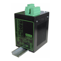
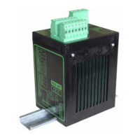
Identification of terminals, LEDs, nameplate, and controls on the RESISTRON RES-407 controller.
Guidance on configuring the controller via DIP switches, coding switches, and plug-in jumpers for optimal operation.
General information, burning-in process, and replacement procedures for heatsealing bands used with the controller.
Step-by-step guide for initial startup, calibration, and testing of the RESISTRON temperature controller.
Explanation of the LEDs and their states indicating controller operation, alarms, and calibration status.
Methods for setting the desired heatsealing temperature using voltage input or a potentiometer.
How the controller outputs the actual measured temperature as an analog signal for monitoring.
Process and prerequisites for the automatic calibration function to match the controller to system signals.
Function of the START signal to enable heating and comparison of set vs. actual temperature.
How the RESET signal aborts cycles, stops measurements, and clears error messages.
Setting the duration of measuring impulses for specific application requirements.
Function to compensate for phase angle displacement in special heatsealing applications.
How the controller checks actual temperature against settable tolerance bands for fault detection.
Monitoring the time taken for the actual temperature to reach 95% of the set temperature.
Using the interface and software for system diagnostics and process visualization.
Features for fault diagnosis, selective error messages, and alarm indications via LED and output signal.
Detailed listing and explanation of error codes, their causes, and corrective actions.
Identification of fault areas and their corresponding possible causes for troubleshooting.