Do you have a question about the Toyota 1NZ-FE and is the answer not in the manual?
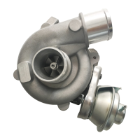
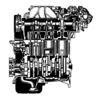
Details the 1NZ-FE engine's configuration and key systems like VVT-i, DIS, ETCS-i.
Illustrates VVT-i operation angles for intake and exhaust valves relative to TDC/BDC.
Lists features related to the engine's core construction and materials.
Lists features related to the valve train components and systems.
Lists features of intake and exhaust components, including manifold and catalytic converters.
Lists features of the fuel delivery system, including injectors and returnless system.
Lists features of the ignition system, highlighting DIS.
Lists features of the engine's electronic control system.
Describes injector placement, water jacket routing, and taper squish combustion chamber.
Discusses aluminum alloy construction and offset crankshaft effect on fuel economy.
Details piston material, taper squish shape for combustion efficiency, and piston pins.
Explains connecting rod material and tightening bolts for weight reduction.
Describes crankshaft pin/journal reduction, journals, balance weights, and sensor rotor integration.
Covers shimless valve lifters, timing chain drive, and VVT-i system overview.
Details oil passages, VVT-i controller, and timing rotor for camshafts.
Explains the roller type timing chain, lubrication, and tensioner mechanism.
Outlines the lubrication circuit, oil pump, filter location, and VVT-i oil control.
Illustrates the flow of coolant through the engine, radiator, and heater core.
Covers plastic intake manifold, linkless throttle body, ETCS-i, and exhaust pipe ball joint.
Details the nonwoven air cleaner element and charcoal filter for emission control.
Explains the linkless throttle body and its DC motor control for throttle valve opening.
Describes the plastic intake manifold's benefits for weight and intake temperature.
Details the exhaust system components, including ball joints for construction and reliability.
Covers fuel returnless system, plastic tank, fuel cut control, quick connectors, and injectors.
Explains how the integrated fuel filter, regulator, and pump reduce evaporative emissions.
Describes the multi-layered plastic fuel tank construction for low permeability.
Details the Direct Ignition System (DIS), coil-integrated igniters, and iridium spark plugs.
Describes long-reach iridium-tipped spark plugs and their benefits for cooling and durability.
Lists specifications for the segment conductor type generator, including voltage and output.
Differentiates between P type and PS type starters used in different regions.
Details the construction of the PS type starter using square conductors and permanent magnets.
Lists the various systems managed by the engine control system (SFI, ESA, ETCS-i, VVT-i, etc.).
Explains starter operation and cranking hold function.
Describes the function of the engine immobilizer system for security.
Explains how malfunctions are diagnosed and logged by the ECM.
Describes the fail-safe mechanisms of the ECM in case of sensor malfunctions.
Lists various sensors used in the engine control system and their signals.
Lists actuators controlled by the ECM and their functions.
Details components related to the canister pump module.
Outlines the evaporative emission control system.
Describes the starter control system and relays.
Explains the control of cooling fan operation.
Mentions the combination meter receiving signals from the ECM.
Lists and describes the functions of the main components of the engine control system.
Describes the ECM's function as a 32-bit CPU for high-speed signal processing.
Explains the output characteristics and function of air fuel ratio and heated oxygen sensors.
Details the construction of planar and cup-type air fuel ratio and oxygen sensors.
Describes the compact mass air flow meter and its built-in intake air temperature sensor.
Illustrates the output voltage of the throttle position sensor relative to valve opening angle.
Shows the output voltage of the accelerator pedal position sensor versus pedal angle.
Introduces ETCS-i, its features, and control functions like IAC and cruise control.
Refers to the throttle position sensor details on page EG-34.
Describes the DC motor used for throttle control and ECM's duty ratio control.
Explains how ECM drives the throttle control motor based on operating conditions.
Details non-linear throttle control for optimal opening based on driving conditions.
Explains ECM control of the throttle valve for ideal idle speed.
Shows fail-safe operation for the accelerator pedal sensor with dual circuits.
Describes fail-safe for the throttle position sensor and throttle control motor.
Explains VVT-i system's function to control intake camshaft timing for economy and emissions.
Describes the VVT-i controller's construction and operation with oil pressure.
Explains the oil control valve's role in applying hydraulic pressure to the VVT-i controller.
Details how advance signals from the ECM control oil pressure for timing advance.
Explains how retard signals from the ECM control oil pressure for timing retard.
Describes how the system holds the target valve timing once achieved.
Illustrates the fuel pump control circuit, including airbag deployment signal.
Introduces the EVAP system's purpose, components, and leak check conditions.
Lists and describes the functions of key EVAP system components like Canister and Purge VSV.
Details the construction and operation of the refueling valve during refueling and purge.
Explains the fresh air line inlet changes and its function in the EVAP system.
Describes the canister pump module's components and its role in leak detection.
Explains ECM control of purge VSV duty ratio to regulate purge flow volume.
Details the ORVR system's operation during refueling and pressure monitoring.
Introduces the EVAP leak check operation and timing chart.
Describes the process of measuring atmospheric pressure for EVAP leak checks.
Details the 0.02 in. leak pressure measurement procedure and DTCs.
Explains the EVAP leak check process and DTCs for small and gross leaks.
Describes the purge VSV monitor procedure and DTC P0441.
Details cooling fan operation based on coolant temperature and A/C status.
Illustrates the system diagram for the cranking hold function.
Shows the timing chart for the cranking hold function during engine starting.
Provides instructions on how to clear stored DTCs.
Explains the fail-safe mechanisms of the ECM in case of sensor malfunctions.
| Displacement | 1.5 L (1497 cc) |
|---|---|
| Compression Ratio | 10.5:1 |
| Fuel System | EFI (Electronic Fuel Injection) |
| Fuel Type | Gasoline |
| Engine Type | Inline 4-cylinder |
| Bore x Stroke | 75.0 mm x 84.7 mm |
| Maximum Power | 80 kW (107 hp) @ 6000 rpm |
| Maximum Torque | 141 Nm (104 lb-ft) @ 4200 rpm |
| Valve Train | DOHC, 16-valve, VVT-i |
| Oil Capacity | 3.7 L (3.9 US qt) |